轻型载货汽车万向传动装置三维设计(含PROE三维图)
轻型载货汽车万向传动装置三维设计(含PROE三维图)(任务书,开题报告,外文翻译,论文说明书8000字,Pro/E三维图)
摘要
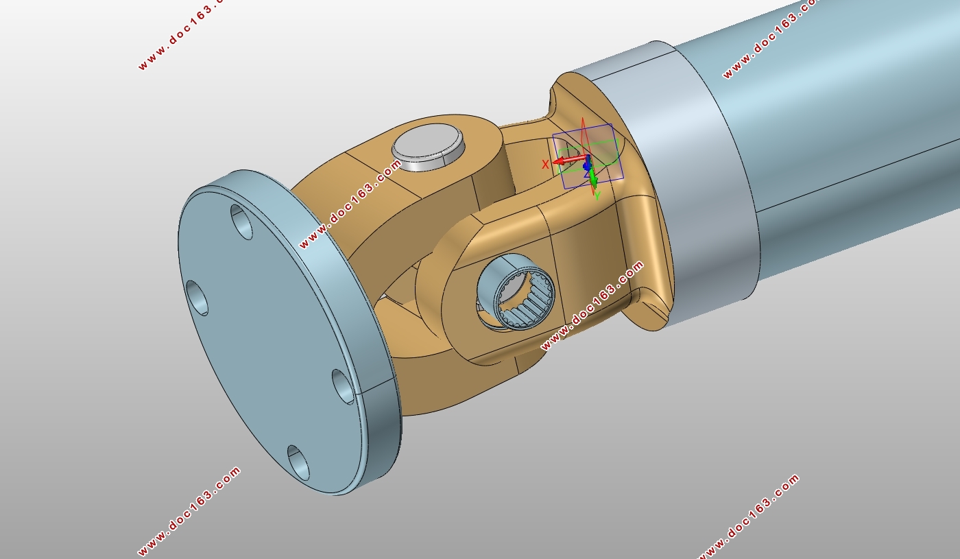
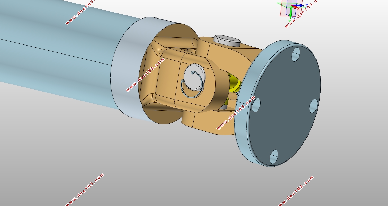
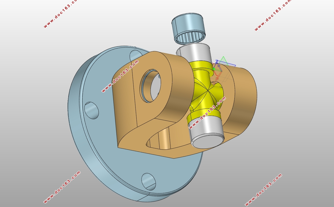
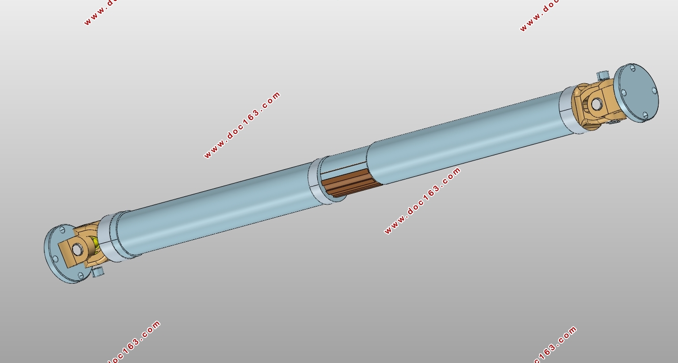
本设计是基于Pro/E软件的轻型载货汽车的万向传动装置的三维设计,万向传动轴是由轴管、万向节、伸缩花键等组成。它主要用于工作过程中相对位置不断改变的两根轴间传递转矩和旋转运动。伸缩套能自动调节变速器与驱动桥之间距离的变化。本文根据汽车工程手册选取轻型载货汽车设计参数,并对万向传动轴的传动载荷进行分析,对十字万向节的尺寸、滚针轴承的尺寸、传动轴的尺寸、花键轴的尺寸、万向节凸缘叉进行设计和计算校核。阐述应用Pro/E软件对万向传动轴的万向节凸缘叉、十字轴总成、中间轴及其连接装置建模的过程,最后进行万向传动装置的总装配,达到了本设计课题的要求。
关键词:轻型载货汽车,万向节,传动轴,建模
Three-dimensional design of light truck's universal transmission device
Abstract
Three-dimensional design of light truck’s universal transmission device based on Pro/E is carried out. The universal transmission device is made up of shaft, universal joint, telescopic spline etc. It is mainly used to work in the process of the relative position changing between the two shaft transmission torque and rotation motion .Expansion sleeve can automatically adjust. In a word, all the sizes meet the needs of the project.
[资料来源:www.doc163.com]
the change of the distance between the transmission and drive axle. In this paper, Light truck’s design parameters are selected according to Automotive Engineering Manual. Next, transmission load of universal transmission shafts is analyzed, the sizes of cross universal joints、needle bearings、transmission shafts、transmission shafts of spline、flange forks of the universal joint are designed and checked. Besides, the modeling process of flange forks of the universal joint、cross universal shafts、intermediate shafts and connected devices are showed by Pro/E. At last, we assemble the universal transmission device.
Keywords: light truck, universal joint, drive shaft, modeling.
2.2轻型载货汽车设计参数
车重:3520kg
发动机的最大输出扭矩: (n=2100r/min);
轴距:2800mm;
车轮滚动半径:310mm;
变速器传动比: 、
主减速器传动比:
满载驱动下一个驱动桥上的静载荷:22425N
[来源:http://Doc163.com]

[资料来源:http://Doc163.com]

目录
摘要 I
Abstract II
第一章绪论 1
1.1发展与现状 1
1.2组成和应用 1
第二章轻型载货汽车万向传动装置结构方案及设计计算 3
2.1万向节结构方案的分析与选择 3
2.1.1十字轴式万向节 3
2.1.2 准等速万向节 4
2.1.3双十字轴万向节传动运动分析 4
2.2轻型载货汽车设计参数 5
2.3设计思路: 5
2.4传动载荷计算 6
2.4.1按发动机最大转矩和一档传动比来计算 6
2.4.2按驱动轮打滑来计算 7
2.5十字轴万向节设计 7
2.5.1初选十字轴万向节尺寸 7
2.5.2十字轴颈作用力合力F的计算 8
2.5.3十字轴颈部的弯曲应力 8
2.5.4十字轴颈部的切应力 9
2.6滚针轴承设计 9
2.6.1滚针轴承初选尺寸 9
2.6.2一个滚针所承受的最大载荷 9
2.6.3滚针轴承的接触应力 10
2.7传动轴初步设计 10
2.7.1万向传动轴的结构分析 10
2.7.2传动轴设计计算 11
2.7.3传动轴强度校核 12
2.8花键轴设计 12
2.8.1花键尺寸的确定 12
2.8.2花键齿侧向挤压应力 13
2.9万向节凸缘叉叉处断面校核 13
2.9.1弯曲应力 14
2.9.2扭转应力 14
第三章基于Pro/E的万向传动轴三维建模 15
3.1万向节凸缘叉的建模 15
3.1.1凸缘的草图 15
3.1.2万向节凸缘叉三维图 16
3.2万向节十字轴总成的建模 16
3.2.1 万向节十字轴建模 16
3.2.2 卡环的建模 18
3.2.3 油封的建模 19
3.2.4 滚针轴承的建模 20
3.2.5 套筒的建模 21
3.2.6 十字轴总成装配 22
3.3花键轴的建模 23
3.3.1外花键的建模 23
3.3.2内花键的建模 24
3.4万向传动轴总装装配方法及三维图 26
3.4.1万向传动轴总装装配方法 26
3.4.2万向传动轴总装装配图 27
第四章 总结 28
4.1设计内容总结 28
4.2体会 28
[版权所有:http://DOC163.com]
参考文献 30
致谢 32
上一篇:汉兰达7座中型SUV转向系统设计(含CAD零件图装配图)
下一篇:七座中型SUV(汉兰达)前制动器设计(含CAD零件图装配图)
