城市SUV前轮转向系设计(含CAD零件装配图,CATIA三维图)
城市SUV前轮转向系设计(含CAD零件装配图,CATIA三维图)(任务书,开题报告,外文翻译,论文说明书12900字,CAD图7张,PDF图7张,CATIA三维图)
摘 要
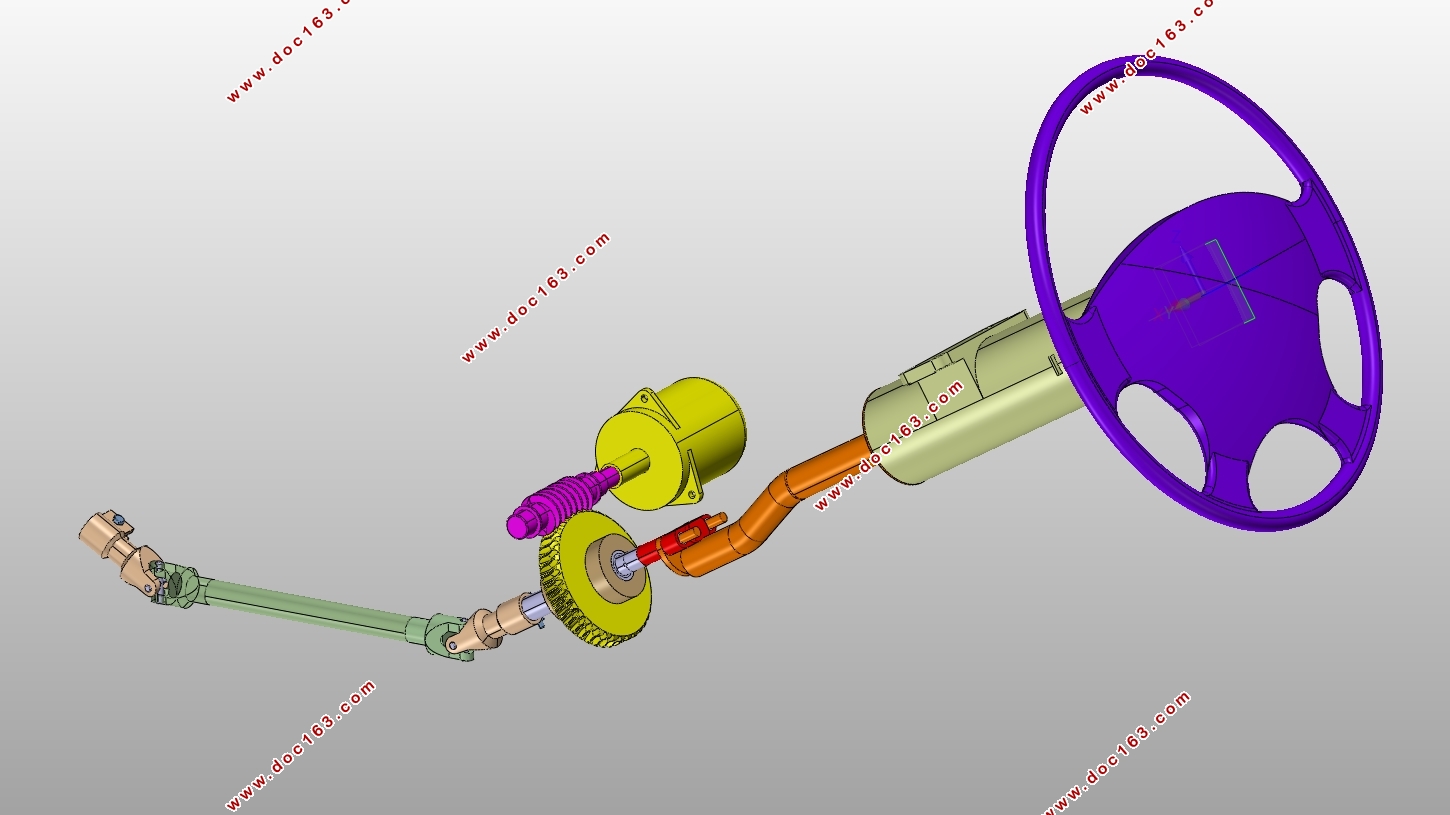
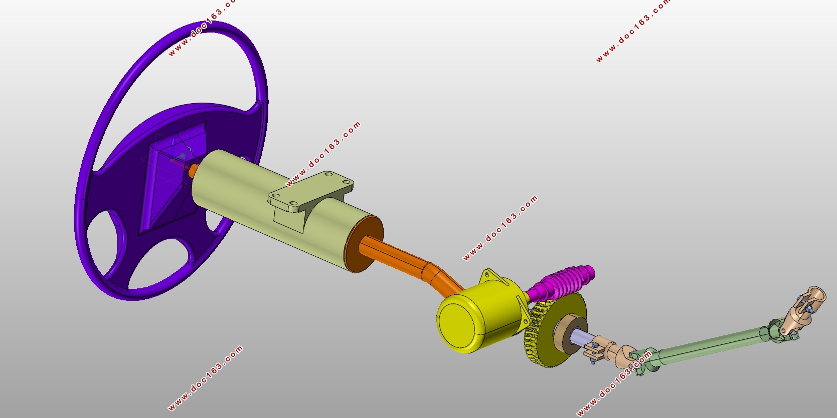
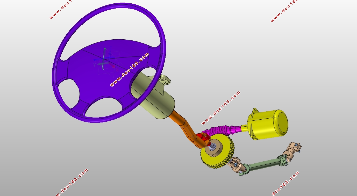
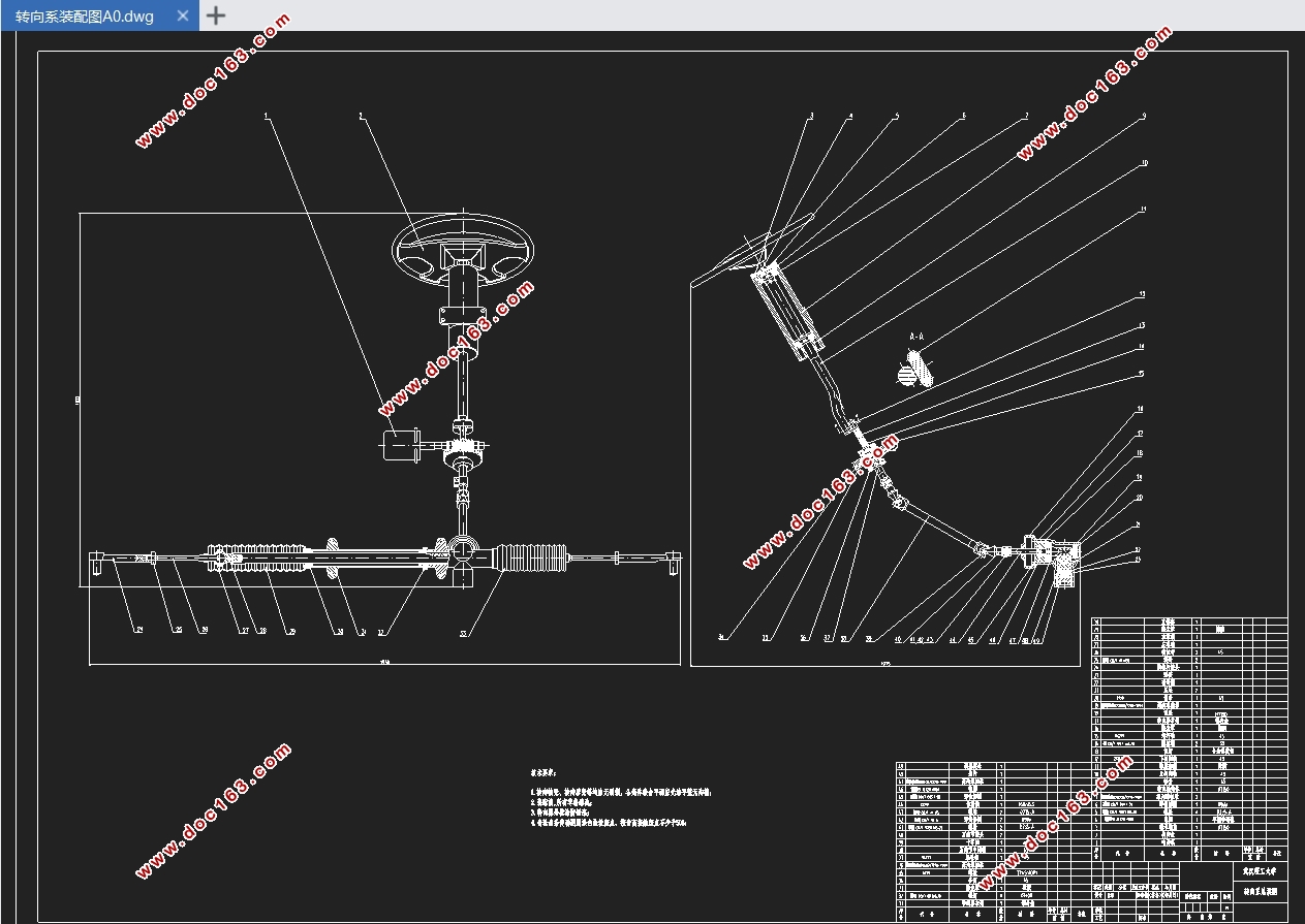
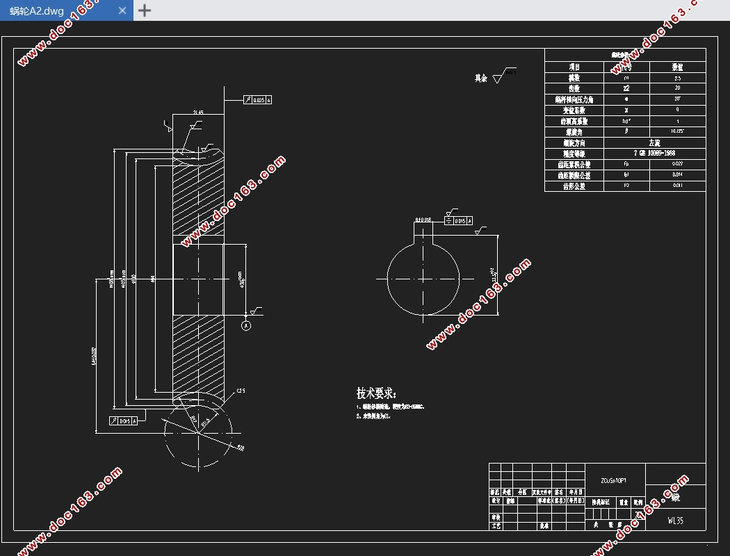
近年来随着驾驶需求的提高,对转向系统的要求也越来越高,电动助力转向系统由于其节能环保,工作效率高,结构布置简单等优点,已经逐渐替代传统的机械式和液压式转向系,应用于越来越多的车型上。本次设计选择车型为长城哈弗H6 2019款,介绍了电动助力转向系统对比液压助力转向的优点,概述了其国内外研究现状、助力转向的工作原理和主要组成部分,对助力部分关键零件进行了选型,并选定了电动助力转向系统的布置形式和齿轮齿条式转向器的结构形式,主要针对齿轮齿条式转向器和蜗轮蜗杆减速机构进行了设计校核,提出了转向传动机构的优化设计方法,最后根据设计参数运用CATIA软件进行了三维建模,绘制了二维转向系装配图和主要零件图。
关键词:电动助力转向系统,齿轮齿条式转向器,蜗轮蜗杆,转向传动机构
Abstract
In recent years, with the increase of driving demand, the requirements for steering system are getting higher and higher. Electric power steering system has gradually replaced the traditional mechanical and hydraulic steering system and been applied to more and more vehicles due to its advantages of energy conservation and environmental protection, high work efficiency and simple structure layout. This design choice models for the Haval H6 2019 model, this paper introduces the electric power steering system compared to the advantages of hydraulic power steering, summarizes the research status at home and abroad, working principle and the main part of the power steering, power part of the key parts for the selection, and selected the decorate a form of electric power steering system and the structure of gear and rack type steering gear, mainly for gear rack type steering gear and worm gear and worm reducer for the design, put forward the optimization design method of steering transmission mechanism, according to the design parameters of 3 d modeling using CATIA software, The assembly drawing and main part drawing of two - dimensional steering system are drawn. [资料来源:http://doc163.com]
Key Words:Electric power steering system, rack and pinion, worm and worm wheel, steering mechanism
汽车参数
方向盘总圈数(n) 3.8
方向盘直径(mm) 380
最小转弯半径(mm) 6000
轮胎规格 235/60 R18 102 H
胎压(MPa) 0.25
轴距(mm) 2680
前轴距(mm) 1625
后轴距(mm) 1625
整备质量(kg) 1661

[资料来源:https://www.doc163.com]


目录
第1章 绪论 1
1.1转向系统简介 1
1.2国内外研究现状 1
1.2.1国内发展状况 1
1.2.2国外发展状况 2
1.3研究目的及意义 3
1.4本章小结 3
第2章 电动助力转向系统 4
2.1电动助力转向系统的组成 4
2.2电动助力转向系统的工作原理 4
2.3助力转向部分的组成部件 4
2.3.1电动机 4
2.3.2扭矩传感器 5
2.3.3电磁离合器 5
2.3.4减速机构 5
2.4电动助力转向系统的布置方案 6
2.4.1转向轴助力式 6
2.4.2齿轮助力式 7
2.4.3齿条助力式 7
2.5汽车参数的确定 8
2.6本章小结 8
第3章 齿轮齿条转向器与减速机构的设计 9
3.1齿轮齿条转向器的方案选择 9 [资料来源:http://Doc163.com]
3.2电动机参数的选择 10
3.3齿轮和齿条的设计计算 13
3.3.1齿轮和齿条基本参数的确定 13
3.3.2齿轮的接触疲劳强度校核 14
3.3.3齿轮的弯曲疲劳强度校核 16
3.4蜗轮蜗杆减速机构的设计计算 17
3.5本章小结 18
第4章 转向传动机构的优化设计 19
4.1转向传动机构布置形式 19
4.2内、外轮实际转角关系 20
4.3优化设计方法 22
4.3.1建立目标函数 22
4.3.2设计变量与约束条件 24
4.3.3优化计算过程 25
4.4本章小结 26
第5章 三维模型的建立 27
5.1转向盘 27
5.2转向轴 27
5.3蜗轮蜗杆 28
5.4齿轮齿条 29
5.5转向系装配体 30
5.6本章小结 30 [来源:http://Doc163.com]
总结 31
参考文献 32
致谢 33
附录 34
[来源:http://Doc163.com]
上一篇:东风本田CR-V前制动系统设计(含CAD零件装配图,CATIA三维图)
下一篇:城市SUV前轮制动器设计(含CAD零件装配图,CATIA三维图)
