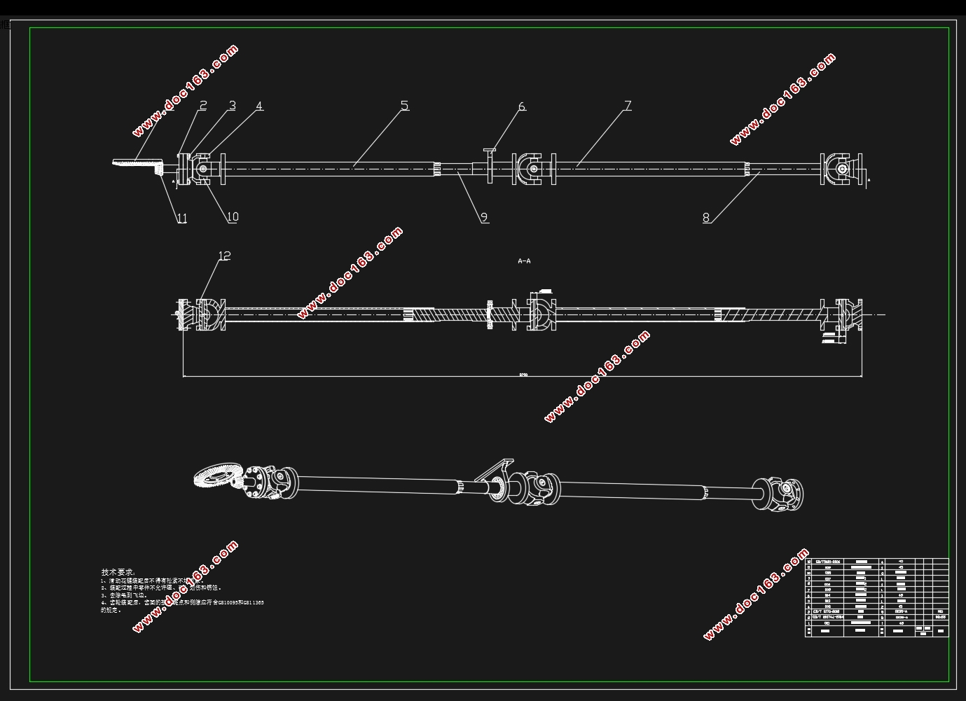
某7座中型SUV万向传动装置设计(含CAD零件图装配图)

某7座中型SUV万向传动装置设计(含CAD零件图装配图)(任务书,开题报告,外文翻译,文献摘要,论文说明书12500字,CAD图9张)
摘要
万向传动装置是汽车传动系中的重要组成部分,它主要用于工作过程中相对位置不断改变的两根轴之间传递转矩和旋转运动。万向传动装置应用广泛,例如发动机前置后轮驱动或前置全轮驱动的汽车中,转向驱动桥的半轴等。本次设计的是某七座中型SUV的万向传动装置。它的主要零件包括万向节、传动轴及中间支承。万向节是两根轴之间实现变角度传递动力的部件,其种类较多,最常用的是十字轴式万向节。传动轴总成由轴管及伸缩花键等组成。对于长轴距的汽车,还会有中间支承。在本次设计中,首先介绍了万向传动装置的国内外研究现状,接着确定了各零件的结构方案,然后对其进行设计计算和校核,最后利用CATIA软件进行了三维建模,利用CAD制作了零件的二维图。
关键词:万向传动装置;万向节;传动轴
Abstract
The universal transmission device is an important part of the automobile transmission system.It is mainly used for the transmission torque and rotational motion between two shafts which the relative position of the working process is constantly changing.Universal transmission device is widely used in the engine front wheel or all wheel drive car or steering drive axle shaft and so on.The goal of this design is the universal transmission device of seven - sized SUV. Universal joint assembly is comprised of universal joint and transmission shaft, andthe middle support, in some cases. The universal joint is the basic component of the transmission power of changing angle between two shafts. It have a great variety. And the cardan joint is the most commonly used. Driving shaft assembly is composed of an axle tube and a telescopic spline. There will be an intermediate support for long wheelbase cars. In this design,First of all, we introduce the research status of universal drive device at home and abroad. And then we determine the structure scheme of each part. Then it carries on the design calculation and the check. Finally, using CATIA to carry on the three dimensional modeling and using CAD to produce parts of the two-dimensional map. [资料来源:https://www.doc163.com]
Keywords:universal transmission device;universal joint;transmission shaft
表2.1汽车基本参数
发动机转矩 350
最大扭矩转速 2000rpm
整车整备质量 2000Kg
轴距 2790mm
变速器一档传动比 3.300
主减速器传动比 4.398
轮胎规格 245/60 R18
[版权所有:http://DOC163.com]


目 录
摘要 I
[资料来源:http://Doc163.com]
Abstract II
第1章 绪论 1
1.1课题的背景及意义 1
1.2万向传动装置的发展及国内外研究现状 1
1.3设计的主要内容及目标 2
第2章 万向传动装置结构方案确定 3
2.1设计已知参数 3
2.2结构方案确定 4
2.2.1 万向传动轴结构形式的确定 4
2.2.2传动轴的选择 5
2.2.3中间支承选择 5
2.2.4万向节的选择 6
第3章 万向传动装置设计 10
3.1 万向节传动的计算载荷 10
3.2 十字轴万向节设计 11
3.2.1十字轴的设计 11
3.2.2十字轴滚针轴承设计 12
3.2.3十字轴万向节叉的设计 13
3.2.4万向节的传动效率校核 15
3.3传动轴1的计算与强度校核 16
3.3.1传动轴的临界转速 16
3.3.2传动轴的强度校核 16
3.3.3花键轴1的设计和校核 17
3.4传动轴2相关计算 18
3.4.1传动轴载荷计算 18
3.4.2十字轴万向节的设计 18
3.4.3传动轴结构设计及转速校核 18
3.5等速万向节设计 19
3.5.1计算载荷的确定 19
3.5.2万向节尺寸确定 20
3.6分动器齿轮设计 21
3.6.1齿轮许用应力的确定 21
3.6.2 锥齿轮设计 22
3.6.3 锥齿轮校核 23
第4章 结论 25
参考文献 27
附录 28
致谢 31
[资料来源:http://www.doc163.com]
上一篇:FSC(方程式汽车)赛车转向系统设计(含CAD零件装配图,CATIA三维图)
下一篇:某7座中型SUV驱动桥设计(以汉兰达为例)(含CAD零件图装配图)
