
东风天龙重型牵引车的转向系统设计(含CAD图,CATIA三维图)
东风天龙重型牵引车的转向系统设计(含CAD图,CATIA三维图)(任务书,开题报告,外文翻译,文献摘要,论文说明书13400字,CAD图10张,CATIA三维图)
摘要
随着我国社会经济的发展和道路交通条件的逐渐改善,大型商用车的使用也越来越广泛。由于重型卡车体型质量较大,驾驶员在操纵转向盘时需要费很大力气,很容易产生疲劳,因此有必要设计一个低成本又有足够助力作用的液压助力转向系统。
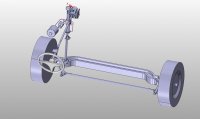
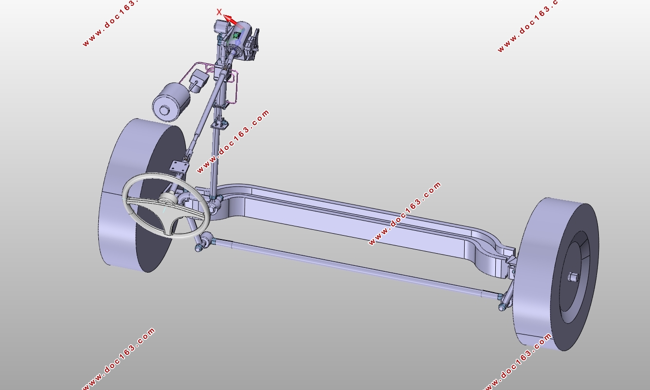
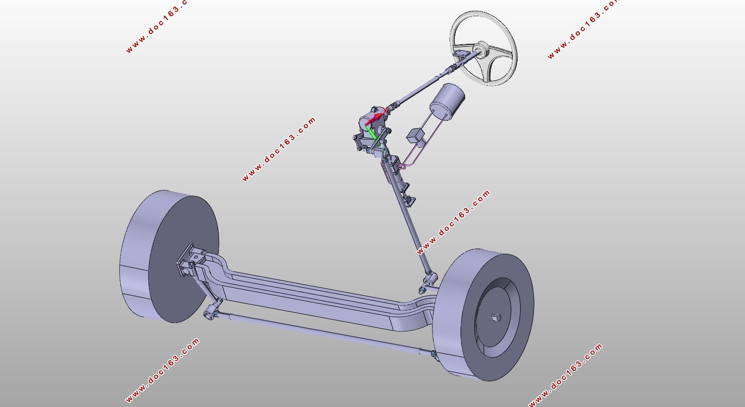
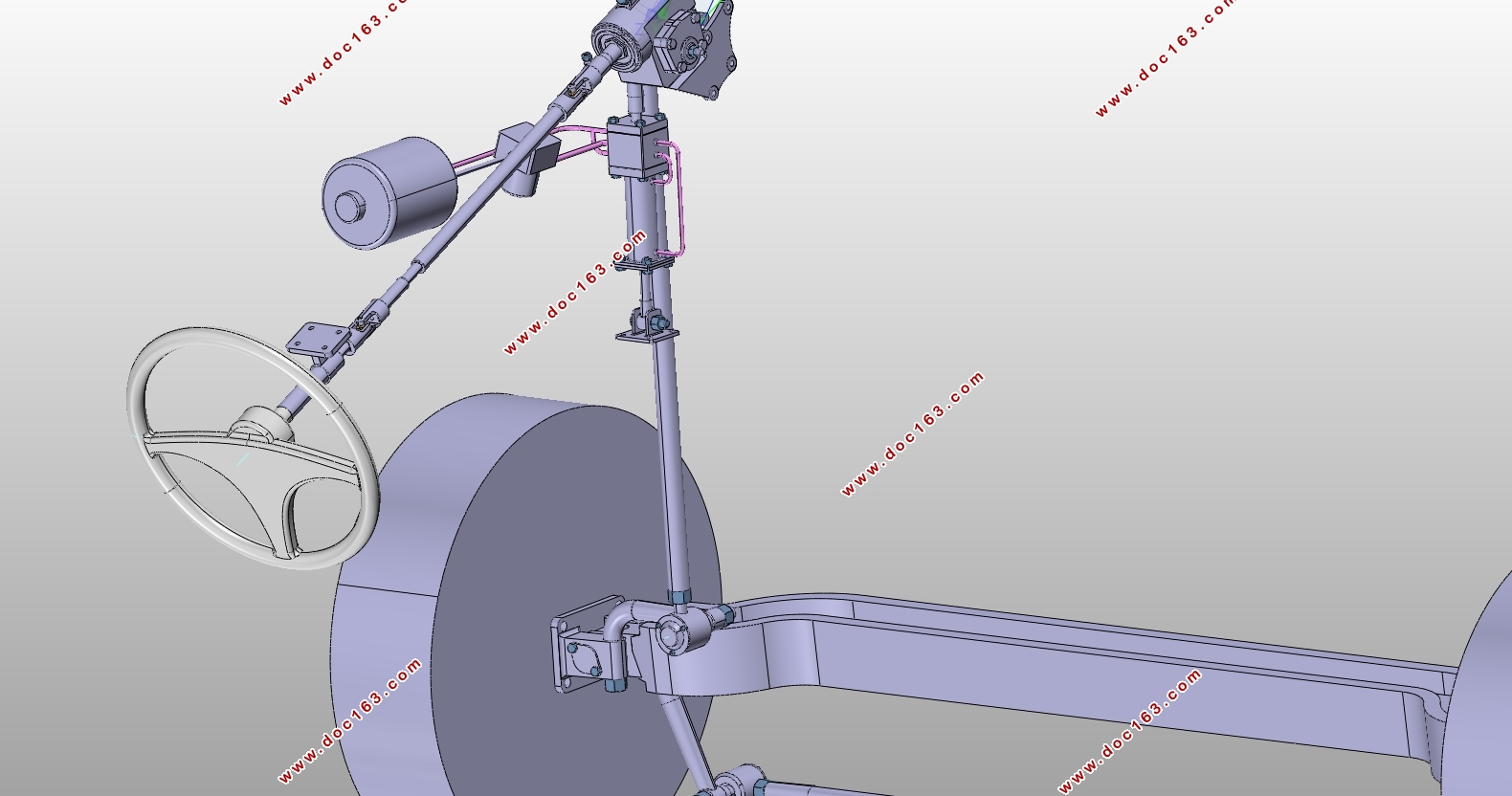
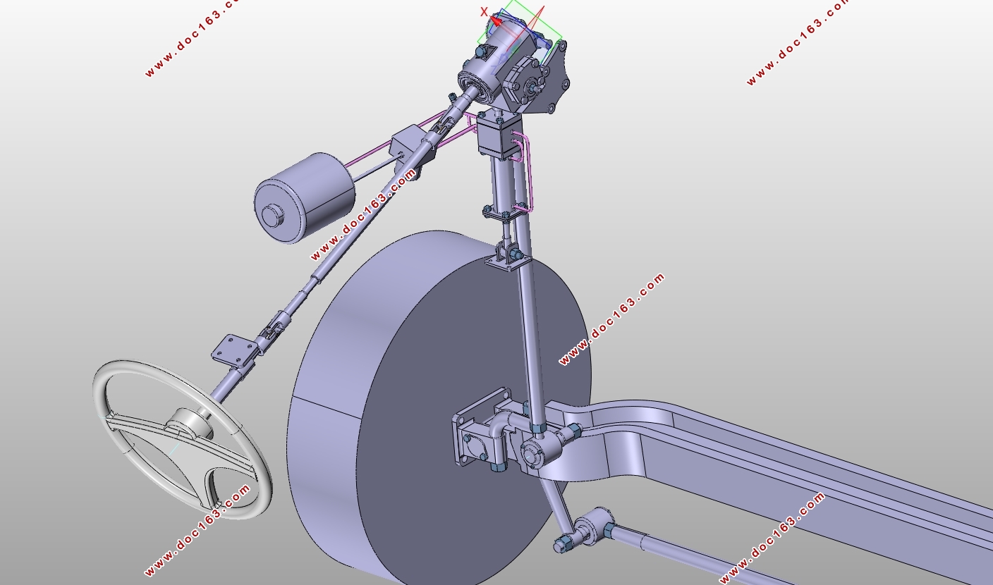
本次设计以东风天龙DFL4251重型牵引车为对象,设计出一个适用于此车型的液压助力转向系统,主要设计内容有:确定设计转向系统所需要的基本汽车参数;转向系统主要性能参数的确定(包括转向系统效率、角传动比和力传动比、传动副的传动间隙等参数);机械式转向器的设计计算(包括转向器的选型、尺寸参数的设计计算、零件强度的校核等);动力转向机构的设计(助力形式的选择、液压转向分配阀的设计、动力缸的设计等);转向传动机构的设计(包括转向桥的设计,转向梯形机构的设计、转向传动部件的设计和强度校核等);转向操纵机构的设计(有转向盘,万向节和吸能防伤装置等)。同时用CATIA软件建立整个转向系统的三维模型并通过AutoCAD将其转化为二维工程图纸。
本次设计先是通过理论的设计计算得到转向系统的各个参数(主要的设计方法和理论来自于汽车设计和机械设计相关资料),然后通过CATIA软件进行三维建模并进行简单的运动学干涉校核来进一步对设计结果进行优化,设计结果满足强度和尺寸要求,安全可靠。本次的设计过程可以作为重型商用车转向系统设计的参考模板,对于其他重型商用车也可采用此流程方法进行转向系统设计。 [版权所有:http://DOC163.com]
关键词:转向系统;循环球;液压助力
Abstract
With the continuous improvement of road traffic conditions in China, the use of large commercial vehicles is becoming more and more popular. Due to the heavy quality of the heavy truck, the driver takes a lot of effort in manipulating the steering wheel, and it is easy to produce fatigue. Therefore, it is necessary to design a low-cost hydraulic power steering system.
In this paper, we take Dongfeng Tianlong DFL4251 heavy-duty tractor as an example to design a suitable hydraulic power steering system.The main design contents are: to determine the basic vehicle parameters needed to design the steering system; to determine the main performance parameters of the steering system (including the steering system efficiency, angular transmission ratio and force transmission ratio, drive the transmission gap); mechanical steering gear design (Including the selection of the power supply, the design of the hydraulic steering valve, the design of the power cylinder, etc.), the steering wheel, the steering wheel, the steering wheel, the steering wheel, the steering wheel, the steering wheel, the steering wheel, the steering wheel, the steering wheel, The design of the mechanism (including the design of the steering axle, the design of the steering trapezoidal mechanism, the design of the steering gear and the strength check, etc.); steering mechanism design (steering wheel, universal joint and energy absorption device). At the same time, CATIA software is used to build the 3D model of the whole steering system and transform it into two-dimensional engineering drawings through AutoCAD. [版权所有:http://DOC163.com]
This design firstreceive the various parametersof the steering system through the theoretical design calculation(the main design methods and theories from the automotive design and mechanical design related information).And then through the CATIA software to build a three-dimensional modeling and simple kinematic interference check to further optimize the design results. Thedesign results meet the strength and size requirements, safe and reliable.The design process can be used as a reference template for heavy-duty commercial vehicle steering system design. For other heavy-duty commercial vehicles, this process can also be used to design the steering system.
Key words:steering system; recirculating ball;hydraulic pressurepower
2.1基本汽车参数的选定
本次设计的车型是东风天龙DFL4251重型牵引车,通过查阅相关资料可以得到转向系统设计所需要的基本参数如下:
表2. 1汽车基本参数
轴距 前轮距 轮胎型号
3300+1350mm 2040mm 295/80R/22.5
轮胎外径 轮胎胎压 整备质量
1043.5mm 0.85Mpa 8.8吨
总质量 轴荷分配
25吨 7000/18000 kg
[资料来源:http://doc163.com]
 [来源:http://www.doc163.com]
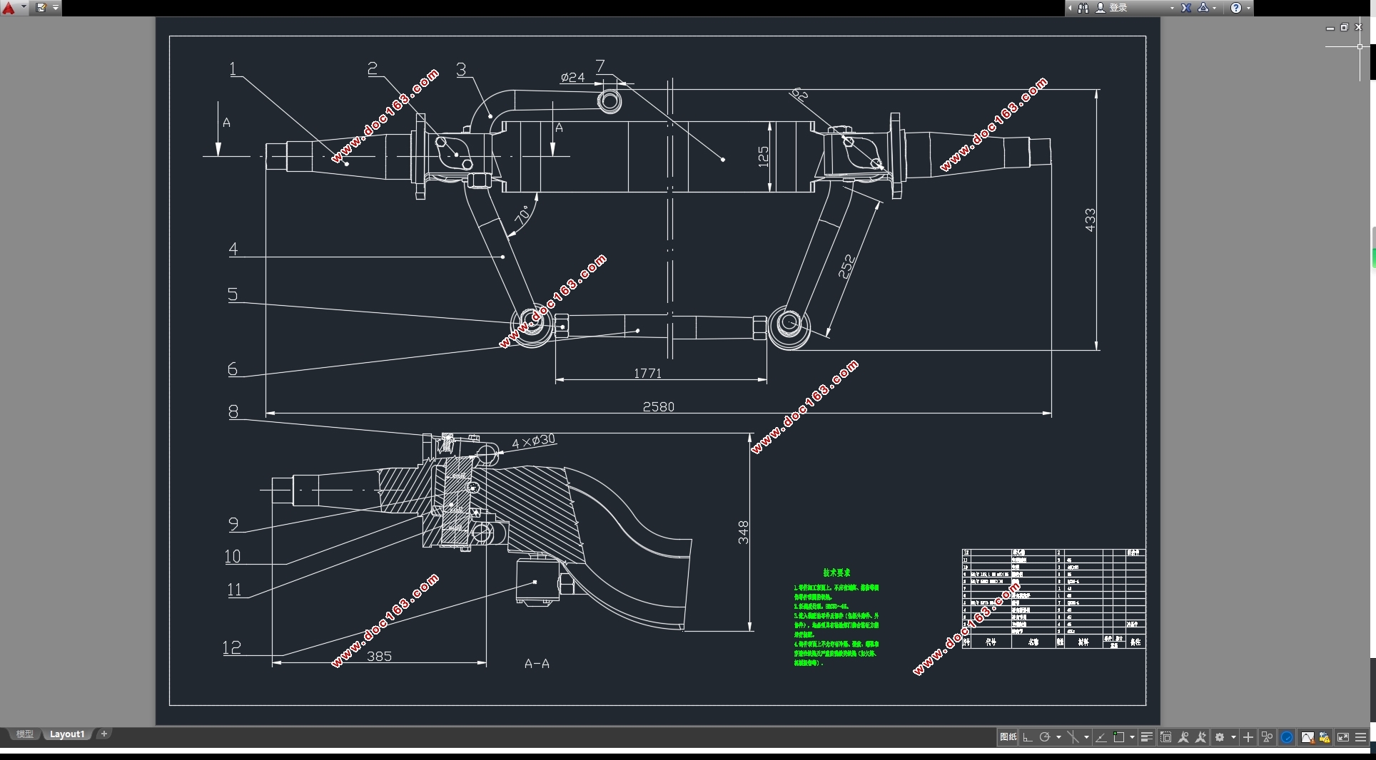

目录
第1章设计任务和要求 1
1.1设计任务 1
1.2设计要求 1
第2章 汽车基本参数和转向系统性能参数的确定 3
2.1基本汽车参数的选定 3 [资料来源:https://www.doc163.com]
2.2转向系统主要性能参数的确定 3
2.2.1转向器的效率 3
2.2.2角传动比和力传动比 4
2.2.3转向器传动副传动间隙Δt 4
2.3 本章小结 6
第3章 机械式转向器设计 7
3.1 转向系统计算载荷的确定 7
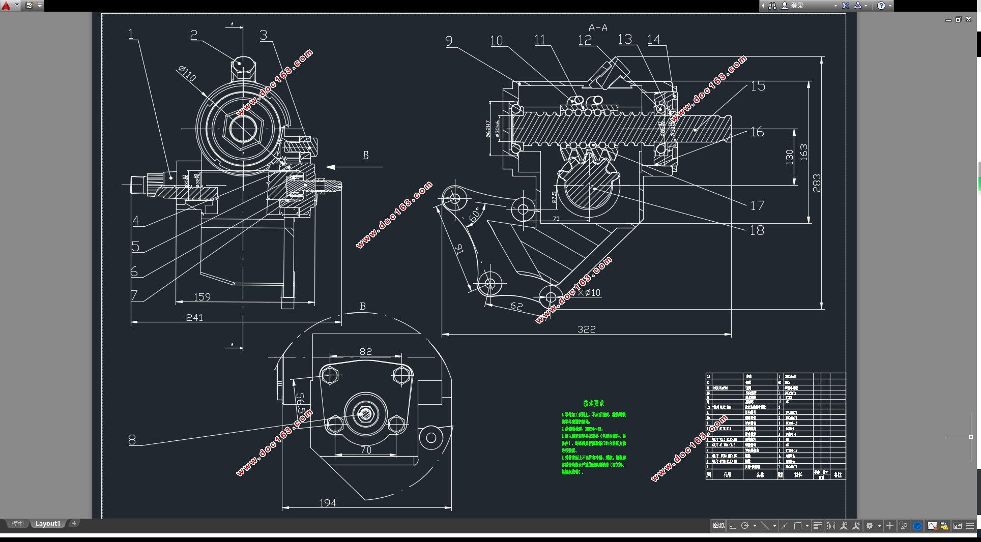
3.2 机械式转向器的设计计算 8
3.2.1机械式转向器的方案选择 8
3.2.2转向器主要尺寸参数的选择 8
3.2.3齿条、齿扇传动副设计 10
3.3转向器零件的强度计算 12
3.3.1钢球与滚道间接触应力 12
3.3.2 齿的弯曲应力 13
第4章 动力转向系统设计 14
4.1 动力系统结构方案的确定 14
4.1.1 对动力转向系统的要求 14
4.1.2动力转向系统结构方案的确定 14
4.2 液压式动力转向机构的计算 16
4.2.1动力缸主要尺寸计算 16
4.2.2 分配阀参数的选择 18
4.3 动力转向器的评价指标 20
4.4 本章小结 20
第5章 转向传动机构设计 22
5.1转向从动桥设计 22
5.1.2工字梁设计与强度计算 22
5.1.3 主销设计和强度计算 23
5.1.4 转向节强度计算 25
5.2 转向梯形机构设计 25
5.3 转向传动部件设计 27
5.3.1球头销 27
5.3.2转向摇臂 28
5.4 本章小结 28
第6章转向操纵机构设计 30
6.1 转向盘布置及尺寸 30
6.2 转向轴的防伤安全措施 30
6.3万向节的设计计算 31
6.3.1万向节的选型 31
6.3.2十字轴万向节的计算校核 31
第7章 设计总结 34
参考文献 35
致谢 36
上一篇:分散多动力纯电动轿车转向系设计(含CAD零件图装配图)
下一篇:东风猛士EQ2050B的制动系统设计(含CAD图,CATIA三维图)(英文版)