某7140型轿车后悬架设计及多体动力学分析(含CAD图,CATIA三维图)
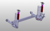
某7140型轿车后悬架设计及多体动力学分析(含CAD图,CATIA三维图)(任务书,开题报告,外文翻译,论文说明书9300字,CAD图5张,CATIA三维图)
摘要
汽车悬架是汽车行驶系非常重要的一部分,汽车悬架的主要功能是传递车身与轮胎之间的力与力矩。悬架的减震器与弹性元件能起到缓冲、减振、保证汽车稳定行驶的作用。当今社会,人们提高了对汽车的舒适性的要求,这需要设计出性能更加优异的悬架,使汽车具有更好的平顺性与操纵稳定性。
研究本课题时,整车数据参考捷达梦想版汽车,对汽车的后悬架进行设计并运用adams软件对悬架进行动力学和振动分析,设计出满足汽车平顺性要求的悬架系统。在多种悬架系统对比之后,经过多方面比较,为此款捷达汽车选择扭力梁非独立悬架该车的后悬。设计汽车的扭力梁悬架的过程中,先根据汽车的整体参数确定悬架的主要参数如悬架的偏频、悬架的静挠度、悬架的动挠度等。之后再设计悬架弹性元件与减震器的具体参数,其中包括螺旋弹簧的刚度、直径、圈数及减震器的尺寸、阻尼系数等。
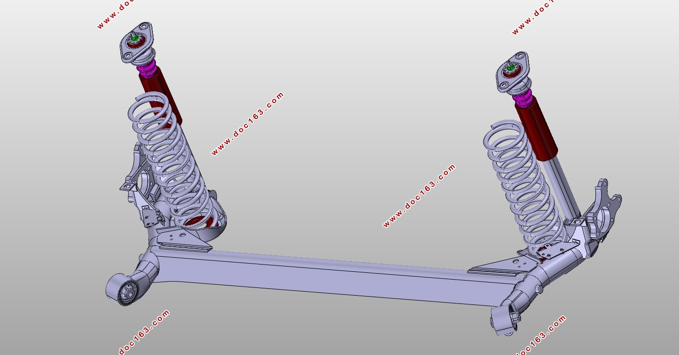
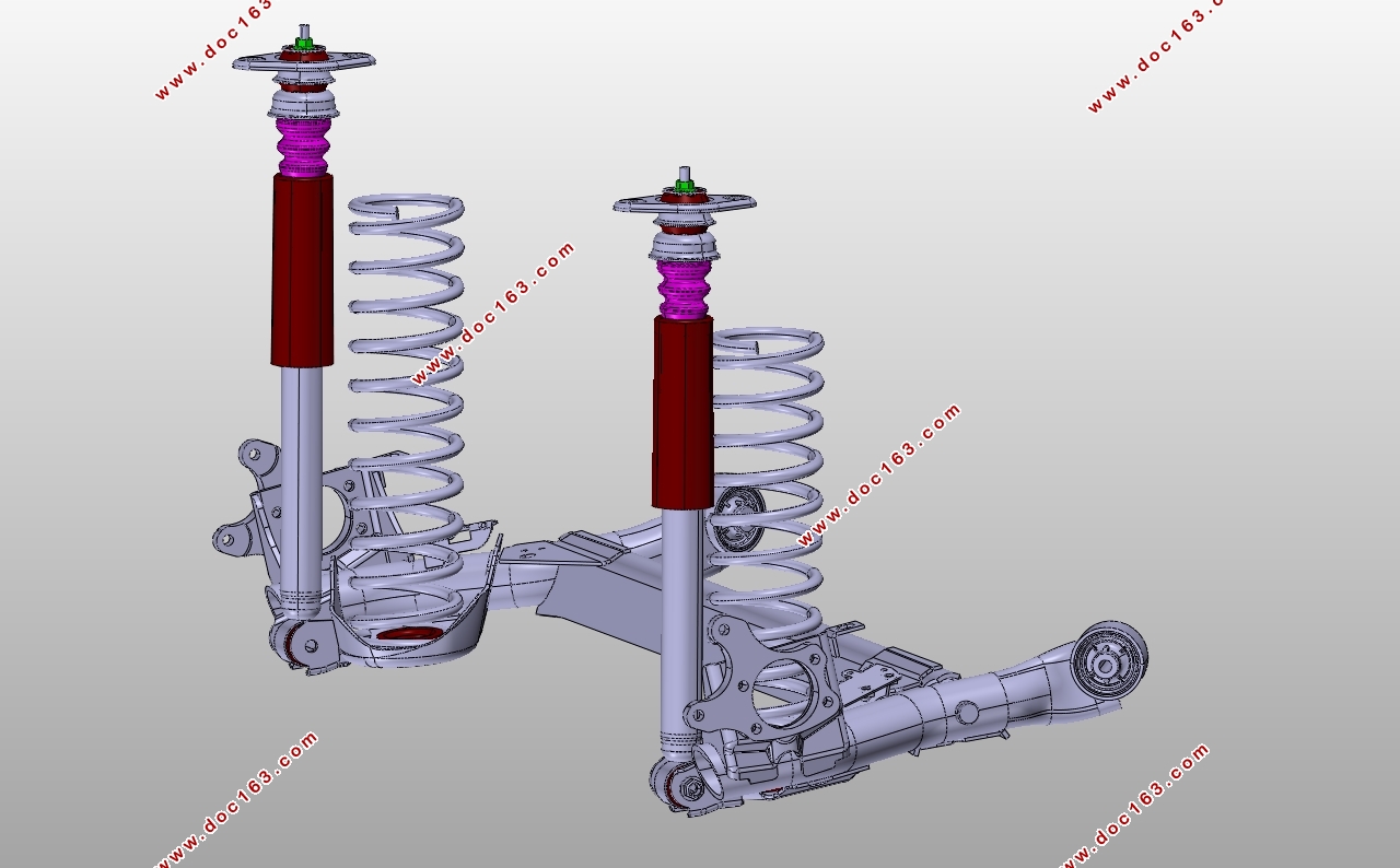
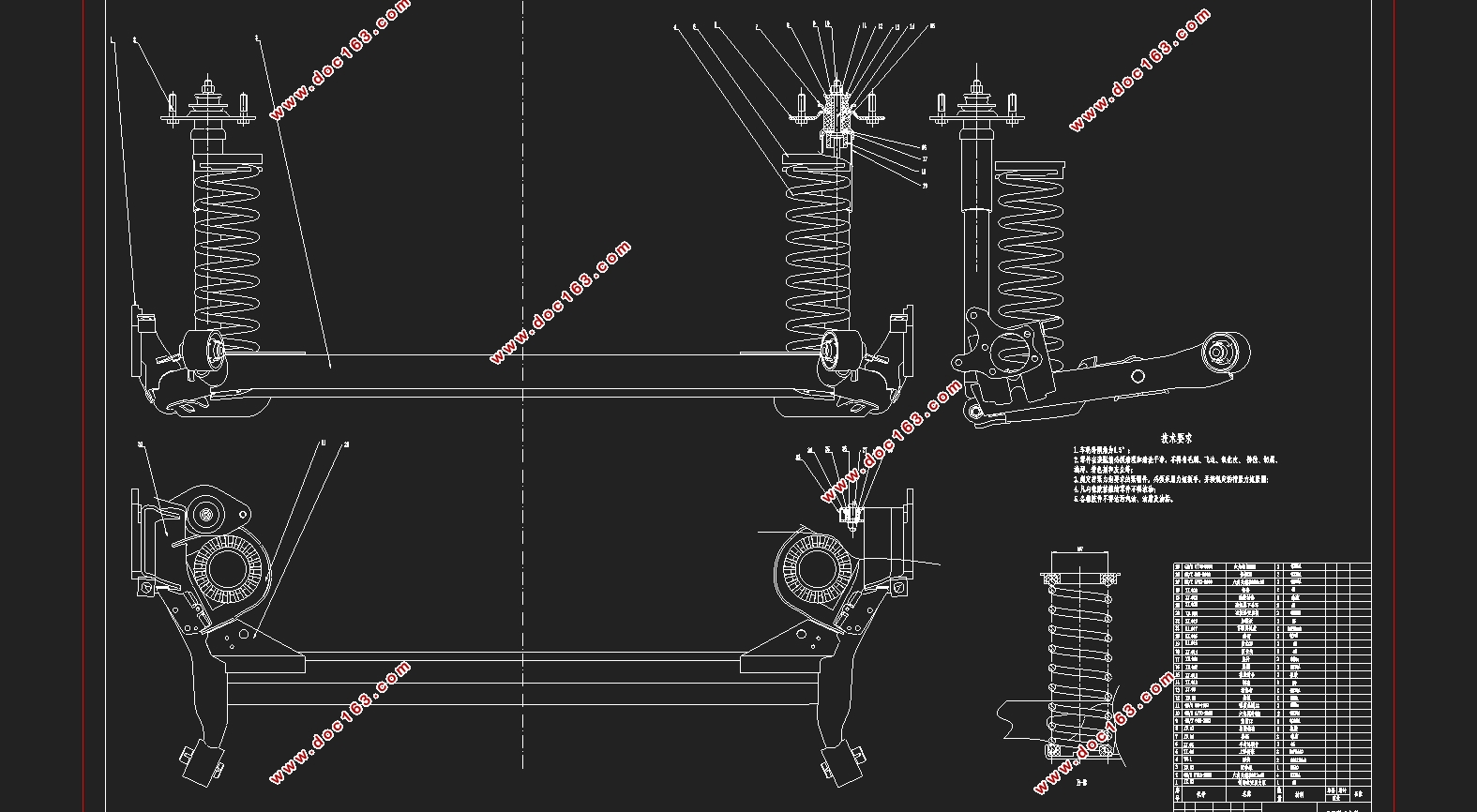
所有参数确定后,使用catia软件对汽车的后悬架进行三维建模装配,根据三维图确定硬点坐标,再利用Adams进行仿真分析,获得汽车受力振动后的整车的参数变化,保证整车的平顺行驶,得到性能可靠的悬架系统。
关键词:扭力梁悬架;三维建模;仿真分析
Abstract
Automobile suspension is a very important part of the automobile driving system. The main function of automobile suspension is to transfer the force and torque between the body and the road. The shock absorber and elastic components of the suspension can play a role in buffering the impact, damping the vibration and ensuring the stable driving of the automobile.At the present stage, people have higher and higher requirements for the riding comfort of the car, which requires the design of a more excellent performance of the suspension so that the car has better ride and handling stability.
Taking the Jetta dream sedan as an example, this paper designs the rear suspension of the automobile and Adams software to carry out multi-body dynamics analysis of the suspension and design the suspension system meeting the requirements of automobile ride comfort.After a variety of suspension system comparison, the torque beam non-independent suspension is selected as the rear suspension ofthis Jetta car.In the process of designing the torsion beam suspension of automobile, the main parameters of the suspension such asthe static deflection, the deflection and vehicle running smoothness are determined according to the vehicle parameters. After that, specific parameters of suspension elastic elements and shock absorber are designed, including stiffness, diameter, winding number of spiral spring, size of shock absorber, damping coefficient, etc.
[资料来源:www.doc163.com]
After all parameters are determined, catia software is used to conduct three-dimensional modeling and assembly for the rear suspension of the car. Hard point coordinates are determined according to the three-dimensional diagram, and then Adams is used for multi-body dynamics analysis to obtain the parameter changes of the whole car after the stress vibration of the car, so as to ensure the smooth running of the whole car and obtain the suspension system with reliable performance.
Keywords:Torsion beam suspension; 3D modeling;Simulation
整车参数
这次毕设课题的主体是某7140型汽车,在此我选择2019款捷达梦想版1.4L 的车型进行汽车后悬架设计,其主要整车参数如下:
1)加速时间(0—100 km/h):11.8s;
2)最小转弯半径:5.3m;
3)整备质量:1120kg;
4)最高车速:181km/h;
5)外形尺寸(长 宽 X高):4501mm 1704mm 1469mm;
6)轴距:2775mm;
7)前轮距:1560mm;
8)后轮距:1560mm;
9)驱动方式:前置前驱,发动机横置;
[资料来源:http://Doc163.com]
10)最大功率/转速:66kW/ 5500r/min(rpm);
11)最大扭矩/转速:132Nm/ 3800r/min(rpm);
12)轮胎规格:185/60 R15。
13)前悬LF:963mm
14)后悬LR: 1105mm
[资料来源:https://www.doc163.com]

[来源:http://www.doc163.com]

目录
摘要 I
Abstract II
第一章 绪论 1
1.1 悬架功用 1
1.2 悬架组成 1
[资料来源:www.doc163.com]
1.3 研究背景 1
第二章 悬架方案选择 3
2.1 悬架的分类 3
2.2 悬架类型选择 4
第三章 悬架整体参数设计 6
3.1 悬架设计内容 6
3.2 整车参数 6
3.3 悬架偏频选取 7
3.4 悬架系统的静挠度 7
3.5 悬架系统的动挠度 8
3.6 悬架的刚度 8
第四章 悬架主要零件的设计 9
4.1. 螺旋弹簧设计 9
4.1.1 弹簧刚度设计 9
4.1.2 螺旋弹簧钢丝直径 9
4.1.3 螺旋弹簧的具体参数 11
4.2. 减震器参数设计 12
4.2.1 减震器工作原理 12
4.2.2 阻尼系数的确定 14
4.2.3 最大卸载力F的确定 14
4.2.4 减振器的尺寸设计 15
4.3. 扭力梁的设计 16
4.3.1 扭力杆材料 16
4.3.2 扭杆尺寸 16
第五章 基于adams的悬架分析 18
5.1 Adams简介 18
5.2 悬架运动仿真 18
5.2.1 仿真过程 18
5.2.2 分析结果 19
5.3 悬架振动分析 20
5.3.1 仿真过程 20
5.3.2 分析结果 21 [资料来源:http://www.doc163.com]
第六章 结论 23
参考文献 24
附录A 螺旋弹簧的计算 25
附录B 扭力梁悬架三维图 26
致谢 27
[资料来源:Doc163.com]
下一篇:微型轿车CVT设计与结构有限元计算分析(含CAD图,CATIA三维图)
