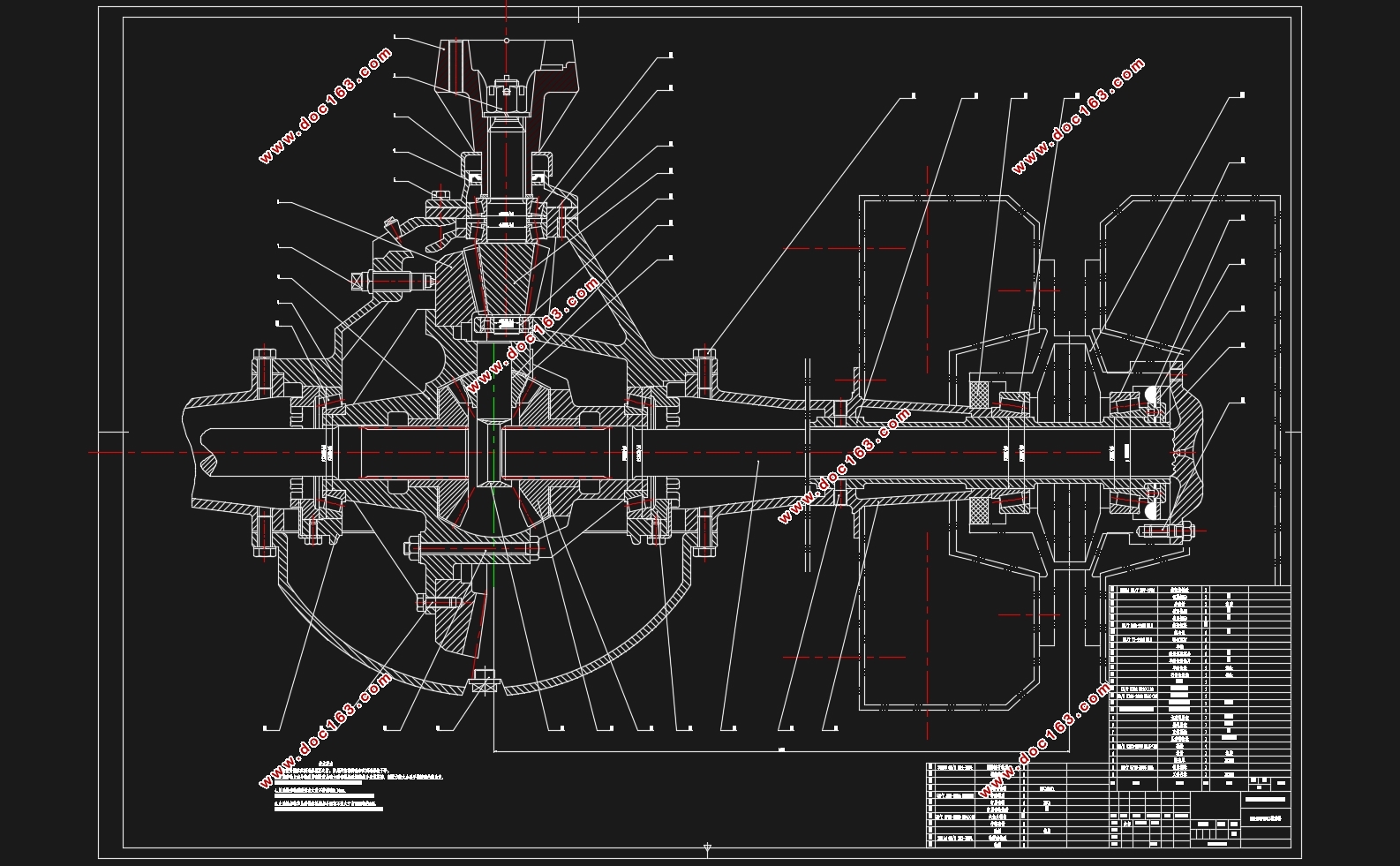
EQ1092F19D1型长头柴油载货汽车驱动桥设计(含CAD零件图装配图)

EQ1092F19D1型长头柴油载货汽车驱动桥设计(含CAD零件图装配图)(任务书,开题报告,文献摘要,外文翻译,论文说明书11000字,CAD图4张)
摘 要
驱动桥被放在运动装置的最末尾的一个位置,它的原始功能是将来自变速器的转矩传递给驱动的车轮表现出速度降低、转矩变大的效应。还要有用地将其配送给左、右车轮,让两个轮子有不一样的转动速度;同时,驱动桥还得接受从地上或车子身体上输送过来的铅锤方位的力和纵平面方位上的力和横平面方位上的力和力矩。
此次设计的车型EQ1092F19D1是中型载货汽车,因此我选用非断开式驱动桥;主减速器采用单级式,采用的是螺旋锥齿轮传动;差速器采用对称式锥齿轮式差速器;半轴选用全浮式;驱动桥壳选用整体式。
通过给定的已知汽车参数,确定驱动桥结构方案,分别计算主减速器,差速器,驱动半轴和驱动桥壳的主要数据,然后确定其构造尺寸,并进行强度计算。最后在计算数据基础上,通过使用AUTOCAD软件来对驱动桥的装配图和零件图进行绘制。
关键词:驱动桥、主减速器、差速器、半轴、整体桥壳
Abstract
the Drive axle is located at the end of power transmission system,its essential function is to add the torque came from the drive shaft or transmission,the torque is allocated to the left and right wheels reasonably and make the left and the right wheels of an automobile with the kinematics differential functional requirements;at the same time, the drive axle also bear vertical forces acting on the body surface or between the longitudinal and lateral forces and torque. [资料来源:www.doc163.com]
The design models EQ1092F19D1 medium-sized truck,so i choose the non-open drive axle ,Single stage main reducer,used the transmission mode is the spiral bevel gear;the symmetrical gear of differential mechanism;full floating axle;the integral drive axle housing.
By a given known vehicle parameters to determine the drive axle structure of the program,and the main parameter of the main reducer,the differential mechanism,the drive axle and the drive axle housing are calculated separately,and then determine the size of the structure.Upon the computational data in the last,i draw assembly drawing and part drawing with AUTOCAD.
Key words:drive axle main reducer differential mechanism drive axle housing
EQ1092F19D1型长头柴油载货汽车的主要技术参数如下表:
表 1.1
最高车速(km/h) 整备质量(kg) 载质量(kg) 前轴轴荷(kg) 后桥轴荷(kg) 发动机型号
83 4810 5000 2410 7600 YC6105QC [资料来源:https://www.doc163.com]
总长(mm) 总高(mm)
总宽(mm) 轴距(mm) 后轮距(mm) 变速器形式
8145 2505 2470 4700 1800 A130机械式、6挡
最小转弯直径(mm) 额定功率(kW/r/min) 最大转矩(N•m/r/min) 轮胎规格 轮辋规格 驱动形式
18 105/2800 402/1700 9.00-20-16PR 7.0-20 4 x 2
[资料来源:www.doc163.com]


目 录
第1章 绪论 1
第2章 驱动桥总成的结构型式选择 2
2.1 技术参数 2
第3章 主减速器设计 3
3.1 主减速器的结构型式 3 [资料来源:http://doc163.com]
3.1.1 主减速器齿轮的类型 3
3.1.2 主减速器主动齿轮的支承型式 4
3.1.3 主减速器从动锥齿轮的支承型式以及安装方式的选择 4
3.1.4 主减速器的减速型式 5
3.2 主减速器的基本参数选择与计算 5
3.2.1 主减速比的确定 6
3.2.2 主减速器齿轮计算载荷的确定 6
3.2.3 主减速器齿轮参数的选择 8
3.2.4 齿轮的强度计算 11
3.3 主减速器齿轮材料 14
3.4 主减速器的润滑 14
第4章 差速器设计 15
4.1 对称式齿轮差速器设计 15
4.1.1 差速器齿轮的基本参数选取 15
4.1.2 差速器齿轮几何尺寸计算 17
4.1.3 差速器齿轮的强度计算 19
4.1.4 差速器齿轮的材料 21
第5章 半轴及桥壳设计 22
5.1 半轴计算载荷确定 22
[资料来源:www.doc163.com]
5.2 半轴杆部直径选择 23
5.3 半轴强度计算 23
5.4 半轴花键强度计算 23
5.5 半轴材料与热处理 24
5.6 桥壳设计 25
第6章 设计小结 26
参考文献 27
致 谢 28
附录 29 [来源:http://www.doc163.com]
上一篇:中级轿车驱动桥设计(含CAD零件图装配图,CATIA三维图)
下一篇:EQ1092F1型长头柴油载货汽车驱动桥设计(含CAD图,CATIA三维图)(英文)
