1240型载货汽车驱动桥设计(含CAD零件图装配图)

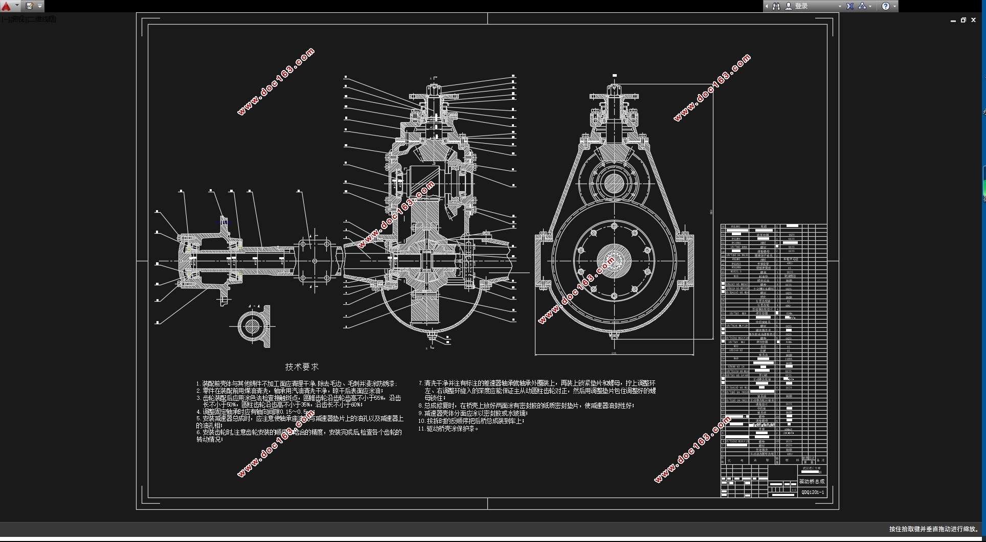
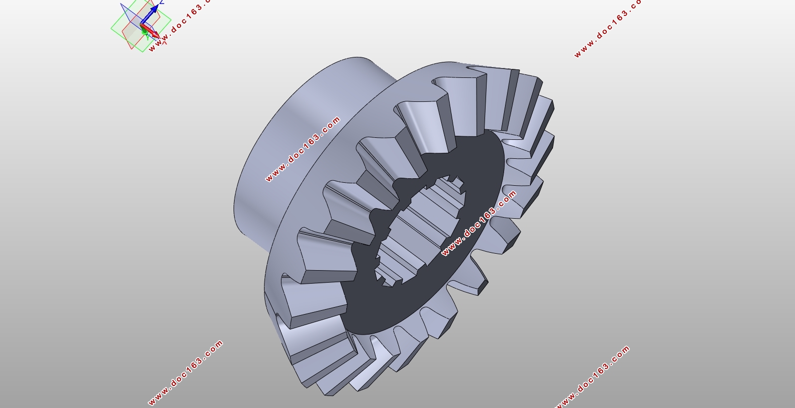
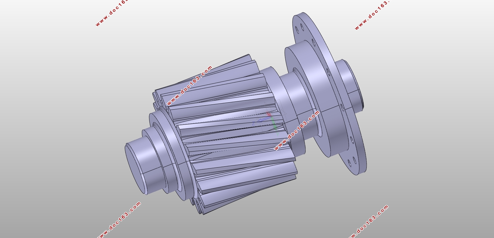
1240型载货汽车驱动桥设计(含CAD零件图装配图)(任务书,开题报告,外文翻译,文献检索,论文说明书10600字,CAD图5张,CATIA中间轴三维图,SolidWorks半轴齿轮三维图)
摘要
伴随着汽车技术的提高和汽车工业的发展,驱动桥的设计和制造工艺都在日益完善。它的性能的好坏直接影响整车性能,而对于载货汽车显得尤为重要。当采用大功率发动机输出大的转矩以满足汽车的需要时,必须要搭配一个高效、可靠的驱动桥。本文首先论述了驱动桥的总体结构,驱动桥各部分结构型式、发展过程,及其以往型式的优缺点的基础上确定了总体设计方案:采用整体式驱动桥,主减速器的减速型式采用双级减速器,差速器采用普通对称式圆锥行星齿轮差速器,半轴型式采用全浮式,桥壳采用铸造整体式桥壳。在本次设计中,主要完成了双级减速器、圆锥行星齿轮差速器、全浮式半轴、桥壳的设计工作。在设计之后对相应的零件进行了校核,并用AUTOCAD和CATIA绘制了相应的图纸。
关键词:驱动桥;双级主减速器;差速器;半轴
Abstract
With the development of automobile industry and the improvement of vehicle technology, design and manufacturing technology of driving axles are increasingly sophisticated. Performance of its directly affects vehicle performance, and it is especially important for trucks. When using high power output of the engine torque to meet needs, we have to have a highly efficient and reliable drive axle. At first, In this dissertation, we first discuss the overall structure of the drive axle. Furthermore, we determine the overall design scheme which is based on the structure type and development of each parts and the pros and cons of the previous model.: useone-piece housing, double reduction final drive, common symmetry bevel planetary gear differential, full floating half axis, casting one-piece axle housing. This design mainly completed the design of double reduction final drive, common symmetry bevel planetary gear differential, full floating half axis and axle housing. After the design, The corresponding parts are checked and draw the corresponding drawings with AUTOCAD and CATIA. [来源:http://www.doc163.com]
Key Words:Driving axle;double reduction final drive;differential;half axis
2.1基本参数
发动机最大功率 kW 170
发动机最大转矩
830
整备质量 kg 9250
满载质量 kg 24250
最高车速 km/h 90
发动机转速 r/min 3000
最小离地间隙 mm 240
滚动半径 mm 493
[资料来源:http://Doc163.com]


[资料来源:http://Doc163.com]
目录
第1章绪论 1
1.1概述 1
第2章设计方案的确定 2
2.1基本参数 2
2.2主减速器的结构方案的确定 2
2.3差速器的选择 3
2.4半轴型式的确定 3
2.5桥壳型式的确定 4
第3章主减速器设计 5
3.1概述 5
3.2主减速比i0的确定 5
3.3主减速器各级传动比确定 5
3.4第一级减速齿轮计算载荷的计算 6
3.5第一级螺旋锥齿轮参数的选择 7
3.6螺旋锥齿轮的计算与强度校核 8
3.6.1螺旋锥齿轮的尺寸计算 8
3.6.2第一级锥齿轮强度校核 9
3.7第二级减速齿轮基本参数的设计 12
3.8主减速器齿轮的材料 15
3.9主减速器部分轴承的计算 15
3.9.1作用在第一级主动锥齿轮上的力 15 [资料来源:http://Doc163.com]
3.9.2第一级齿轮轴承载荷的分析 16
3.9.3轴承的校核 17
3.9.4第二级齿轮传动的力 18
第4章差速器设计 20
4.1差速器的作用 20
4.2 差速器参数设计 20
4.2.1齿轮的基本参数设计 21
4.2.2 差速器齿轮的几何尺寸计算与强度计算 23
第5章半轴设计 27
5.1 半轴的设计与计算 27
5.1.1半轴承受转矩的计算 27
5.1.2半轴的设计 28
第6章驱动桥壳设计 30
6.1受力分析及强度计算 30
6.1.1 桥壳的静弯曲应力计算 30
6.1.2 在不平路面冲击载荷作用下桥壳的强度计算 31
6.1.3 汽车以最大牵引力行驶时的桥壳的强度计算 31
6.1.4汽车紧急制动时的桥壳强度计算 32
结论 35
参考文献 36
附录A 38
附录B 39
致谢 40
[资料来源:www.doc163.com]
上一篇:皮卡车滑板式货箱后斗设计(含SolidWorks三维图)
下一篇:中级轿车驱动桥设计(含CAD零件图装配图,CATIA三维图)
