某汽车空调器支架注塑模具结构设计(含CAD图,SolidWorks三维图)
某汽车空调器支架注塑模具结构设计(含CAD图,SolidWorks三维图)(任务书,开题报告,外文翻译,论文说明书15000字,CAD图5张,SolidWorks三维图,答辩PPT)
摘要
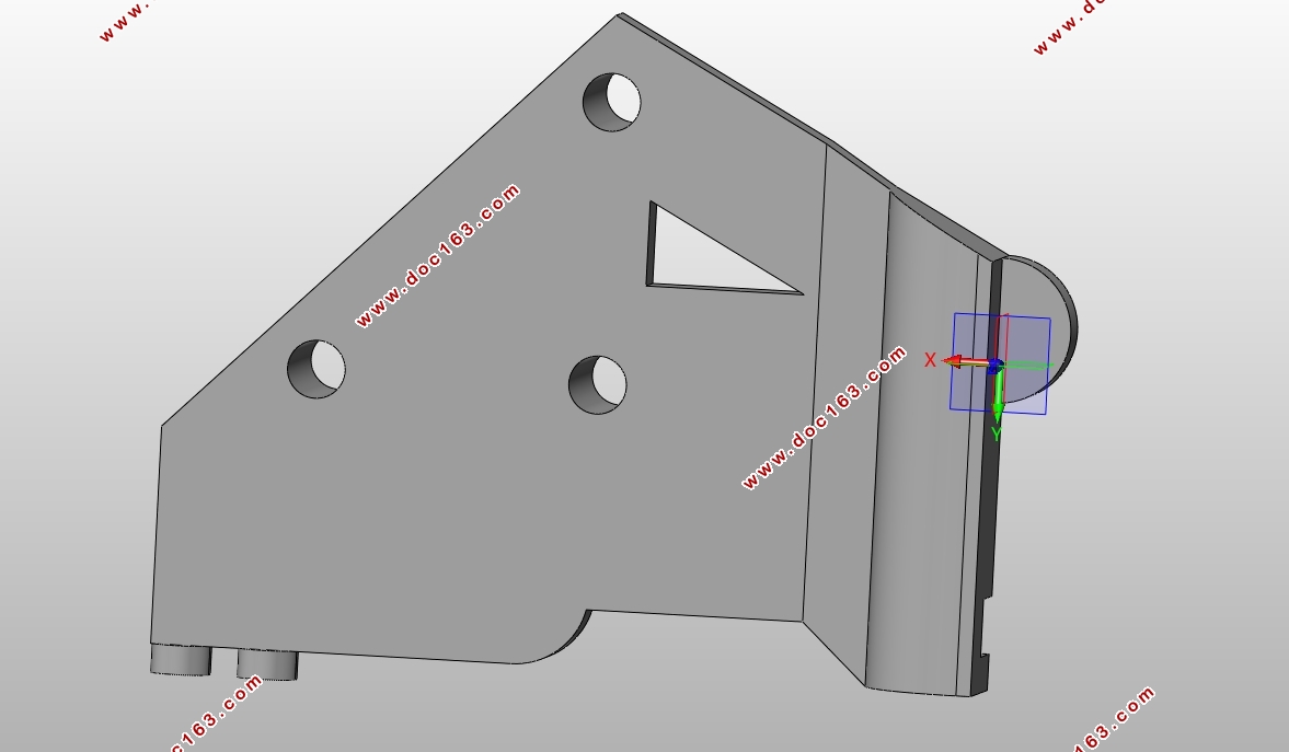
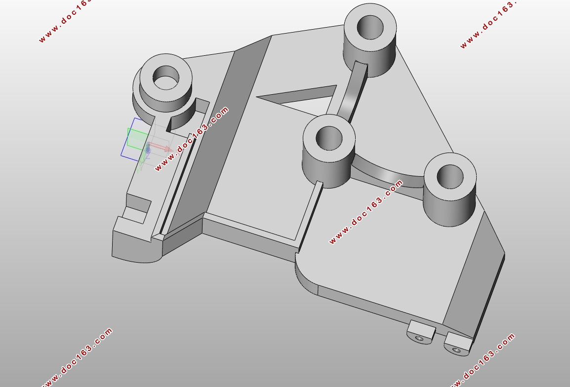
本文利用CAD/CAE技术完成对汽车空调器支架注塑模具结构的设计,主要内容包括以下三个部分,汽车空调支架的三维建模,汽车空调支架注塑过程的数值模拟分析以及详细的模具结构设计。
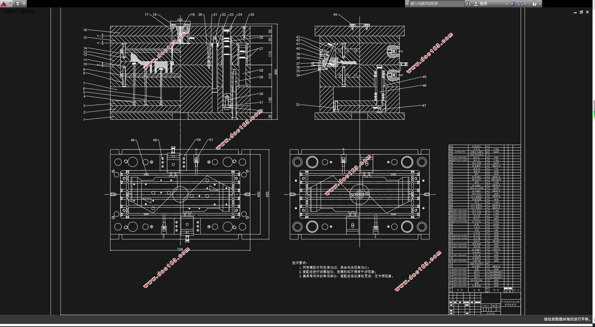
论文首先分析了塑件的结构特点,然后利用SolidWorks对塑件进行三维建模。数值模拟部分,利用Moldflow进行了浇口位置分析、填充分析、翘曲分析。通过浇口位置分析确定了最佳的浇口位置。通过填充分析确定了型腔的数目及布局,并使用控制变量法确定了最佳的填充参数:模具温度、熔体温度及注射时间。通过翘曲分析找出了影响塑件翘曲的主要因素是收缩冷却不均匀,并对其从保压参数、工艺参数、冷却系统三个方面进行了优化。塑件模具的结构设计主要包括浇注系统设计、冷却系统设计、脱膜系统设计和导向定位系统设计。因为此塑件存在侧向凹孔且需多次分型,所以增加了侧向抽芯机构和定距分型机构。此外,本文还包括型芯型腔尺寸的数值计算和推杆、斜导柱等零件的强度校核。
通过本设计,可以对注塑模具的设计过程有一个初步的认识,了解模具的结构,并对其的工作原理有一定的理解。
[版权所有:http://DOC163.com]
关键词:汽车空调支架;侧抽芯机构;定距分型机构;数值分析;模具结构设计
Abstract
In this paper, CAD / CAE technology is used to design the structure of injection mold for automobile air conditioner. The main contents are as follows: three-dimensional modeling of automobile air-conditioning bracket, numerical simulation analysis of injection molding process of automobile air-conditioning support and detailed mold structure design.
Firstly, the paper analyzes the structural characteristics of the plastic parts, and then uses SolidWorks to model the plastic parts in three dimensions. In the numerical simulation part, the gate position analysis, filling analysis and warping analysis were carried out by using moldflow. The optimal gate position was determined by gate position analysis. The number and layout of the cavities were determined by filling analysis, and the optimal fill parameters were determined using the control variable method: mold temperature, melt temperature and injection time. The main factors that affect the warpage of the plastic parts are the uneven cooling and the optimization of the compression parameters, the process parameters and the cooling system. The structural design of the plastic mold mainly includes the design of the pouring system, the design of the cooling system, the design of the stripping system and the design of the guiding system. Because this plastic part of the existence of lateral concave and need to be sub-type, so the increase of the side of the core pulling mechanism and the type of sub-type institutions. In addition, this article also includes the core cavity size of the numerical calculation and putter, diagonal guide column and other parts of the strength check.
Through this design, you can have a preliminary understanding of the design process of injection mold, understand the structure of the mold, and its working principle have a certain understanding..
Key Words:Automotive air conditioning bracket; side core pulling mechanism; fixed pitch type mechanism; numerical analysis; mold structure design
[来源:http://www.doc163.com]

[来源:http://www.doc163.com]

目录
第1章绪论 1
1.1研究的目的与意义 1
1.2国内外研究现状及发展前景 1
1.2.1国外研究现状及发展 1
1.2.2国内研究现状及发展 2
1.3论文的研究内容 2
1.4拟采用的技术方案及措施 2
1.4.1采取的措施 2
1.4.2技术路线 3
1.5小结 4
第2章汽车空调支架的注塑成型分析 5 [资料来源:www.doc163.com]
2.1 Moldflow软件介绍 5
2.2分析的目标 5
2.3 模流分析的流程图 5
2.4 分析前的准备 6
2.4.1 网格划分 6
2.4.2 网格修复 6
2.5 浇口位置分析 7
2.6成型窗口分析 7
2.7填充分析 8
2.7.1 填充时间 8
2.7.2 速度/压力切换时压力 8
2.7.3 充填结束时压力 9
2.7.4 熔接线 10
2.8填充分析优化 11
2.9翘曲分析 11
2.10翘曲分析优化 12
2.10.1 修改保压曲线 12
2.10.2 改变最大保压压力 13
2.10.3 改变保压时间 14
2.10.4 修改工艺参数 15
2.10.5 改进冷却系统 15
2.11小结 16
第3章注塑机的选择 17 [版权所有:http://DOC163.com]
3.1 注塑机简介 17
3.2 注射机的选用 17
3.2.1 根据最大注射量选用 17
3.2.2 根据最大锁模力选用 18
3.2.3 选用注塑机 18
3.3 注射机的校核 19
3.3.1 最大注塑量的校核 19
3.3.2 锁模力的校核 19
3.3.3 喷嘴尺寸校核 19
3.3.4 模具厚度校核 20
3.3.5 开模行程校核 20
3.4 小结 20
第4章汽车空调支架的模具结构设计 21
4.1 汽车空调支架的产品分析 21
4.1.1 ABS的主要性能指标 21
4.1.2 ABS的注射成型工艺参数 22
4.2 汽车空调支架的模具总体方案 22
4.2.1 分型面的选择 22
4.2.2 模具的结构形式 22
4.3 汽车空调支架的成型零部件设计 22
4.3.1 成型零部件的尺寸计算 23 [资料来源:www.doc163.com]
4.3.2 成型零部件的壁厚计算 25
4.4汽车空调支架的模架选择 25
4.5汽车空调支架的浇注系统设计 25
4.5.1 主流道系统的设计 25
4.5.2 分流道系统的设计 26
4.5.3 浇口设计 26
4.6汽车空调支架的脱模系统设计 26
4.6.1 脱模力的计算 26
4.6.2 推杆直径的确定 28
4.6.3 推杆板复位机构 28
4.7汽车空调支架的侧抽芯机构设计 29
4.7.1 抽拔距和抽拔力确定 29
4.7.2 斜导柱尺寸计算 29
4.8汽车空调支架的定距分型机构设计 31
4.8.1 开模顺序 31
4.8.2 定距分型机构的分类 31
4.8.3 定距分型机构 31
4.9汽车空调支架的冷却系统设计 32
4.10 汽车空调支架注塑模具详细结构 33
4.11小结 33 [资料来源:www.doc163.com]
第5章结论 34
参考文献 35
致谢 37
[资料来源:Doc163.com]
上一篇:某汽车前轴锻件锻造工艺设计与仿真分析(含CAD图,CATIA三维图)
下一篇:东风天龙商用车驾驶室前悬置系统设计(含CAD图,CATIA三维图)
