五菱微型汽车5档机械变速器设计(含CAD零件图装配图)

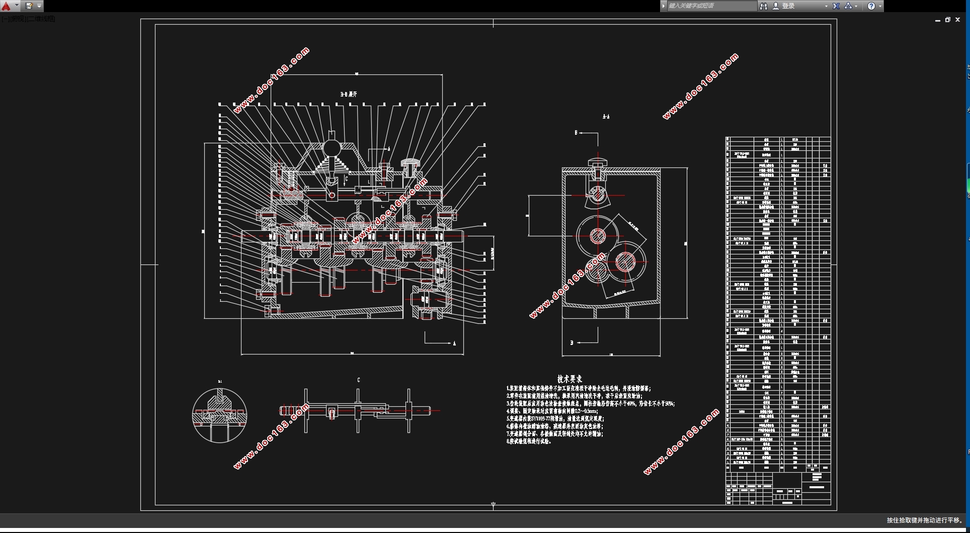
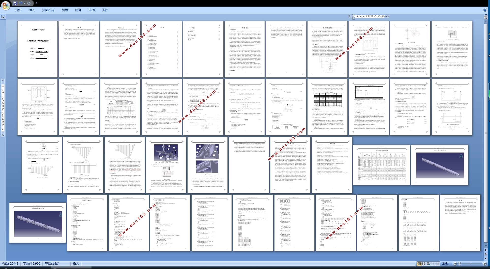
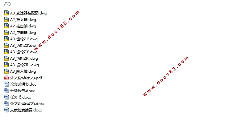
五菱微型汽车5档机械变速器设计(含CAD零件图装配图)(任务书,开题报告,文献摘要,外文翻译,论文说明书14800字,CAD图10张)
摘 要
这篇文章简略地介绍了变速器有什么作用、种类及其在国内外的发展现状和发展趋势,根据任务书要求,参考五菱微型车相关参数设计了一款三轴式的手动五挡机械变速器。设计中首先明确了设计要求,然后对变速器传动机构布置型式、相关零件形式等进行分析和选择,确定了各挡位传动比并确定了各齿轮模数齿数及其他尺寸参数,对轴进行了结构和尺寸设计以及选择了轴承型式型号,对齿轮和轴进行了必要的强度校核,设计了一种单轨式操纵机构,最后根据设计结果绘制了变速器了装配图和主要零件图。
关键词:五菱微型车;变速器;五挡;三轴式
Abstract
This article introduces the function, variety, development status and tendency of automotive transmission, according to the acquirements of assignment, a tri-axial 5-gear manual transmission is designed referred to some related parameters of Wuling vans. Firstly the design demands are confirmed, and the layout arrangements of transmission mechanism and component types are analyzed, while the applicable solutions are selected, the gear ratio is calculated so as the geometrical dimensions of every gear including module and number of teeth, the structure and size of shafts are designed, after that the specific type of bearings for shafts and gears is also confirmed, a single rail gear shift system is designed for a this 5-speed manual transmission, importantly, strength checking calculation is conducted on main components to ensure their security, after all the assembly drawing of the transmission and part drawing of some parts on it are made based on calculation and design consequences. [来源:http://Doc163.com]
Key words: Wuling van;transmission;5-gear;tri-axial
[资料来源:http://www.doc163.com]


目 录
摘 要 I
Abstract II
目 录 0
第1章 绪论 1
1.1变速器功用 1
1.2变速器种类及发展现状 1
1.3设计要求 1
第2章 变速器设计 3
2.1传动机构类型的选择 3
2.1.1轴的布置 3
2.1.2倒挡布置方案的选用 4
2.2零部件结构形式初选 4
2.2.1齿轮形式的选择 4
2.2.2换挡机构型式 5
2.2.3轴承形式选择 6
2.3变速器主要参数的选择 6
2.3.1挡位数及传动比的选择 6
2.3.2齿轮参数选择 9
2.3.3中心距的初步计算 10
2.3.4变速器壳体尺寸初选 11
2.4齿轮几何尺寸计算及强度校核 11
2.4.1确定各挡齿轮齿数 11
2.4.2齿轮强度校核 12
2.5同步器设计 14
2.5.1同步器类型 14
2.5.2同步器主要尺寸、参数设计 14
2.6轴的设计与校核 16
2.6.1轴的结构与尺寸设计 16
2.6.2轴的校核 16
2.7操纵机构的结构设计 19
2.7.1操纵机构概述 19
2.7.2结构设计 20
2.7.3工作原理 20
2.8壳体结构设计 22
第3章 总结 24
参考文献 25
附录A 齿轮尺寸参数 26
附录B 拨叉轴三维图 27
附录C 输出轴三维图 28
附录D 计算程序 29
致 谢 38
上一篇:标致307轿车前麦弗逊悬架减振器设计(含CAD零件图装配图)
下一篇:无人纯电动物流车驱动桥设计(含CAD图,CATIA三维图)英文版
