东风猛士EQ2050B的驱动桥设计(含CAD零件图装配图,CATIA三维图)
东风猛士EQ2050B的驱动桥设计(含CAD零件图装配图,CATIA三维图)(任务书,开题报告,论文说明书12000字,CAD图6张,CATIA三维图)
摘要
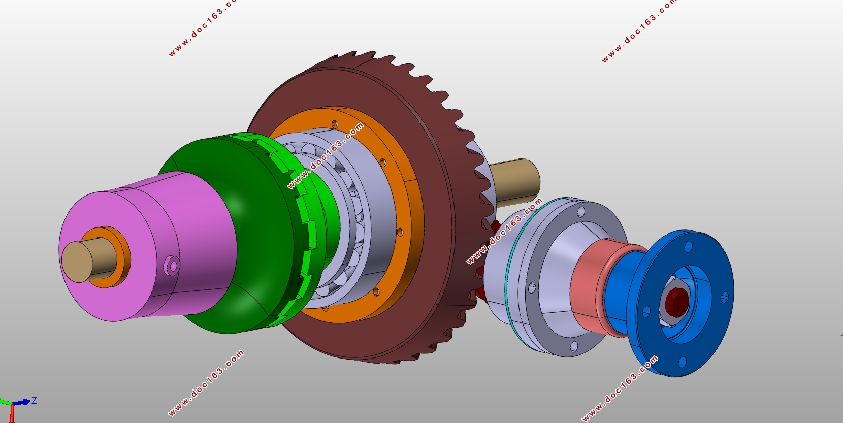
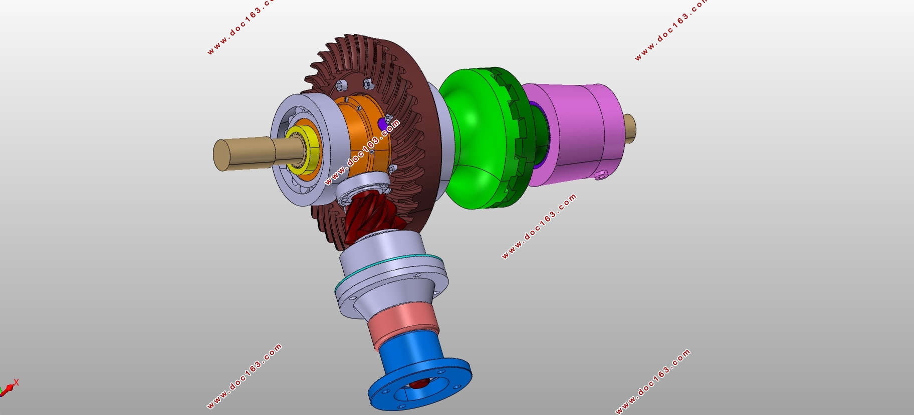
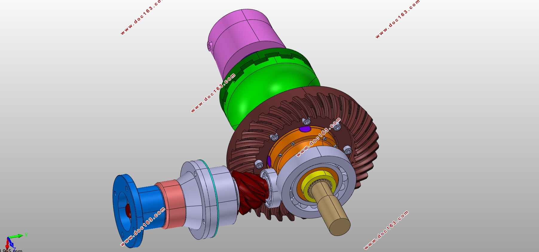
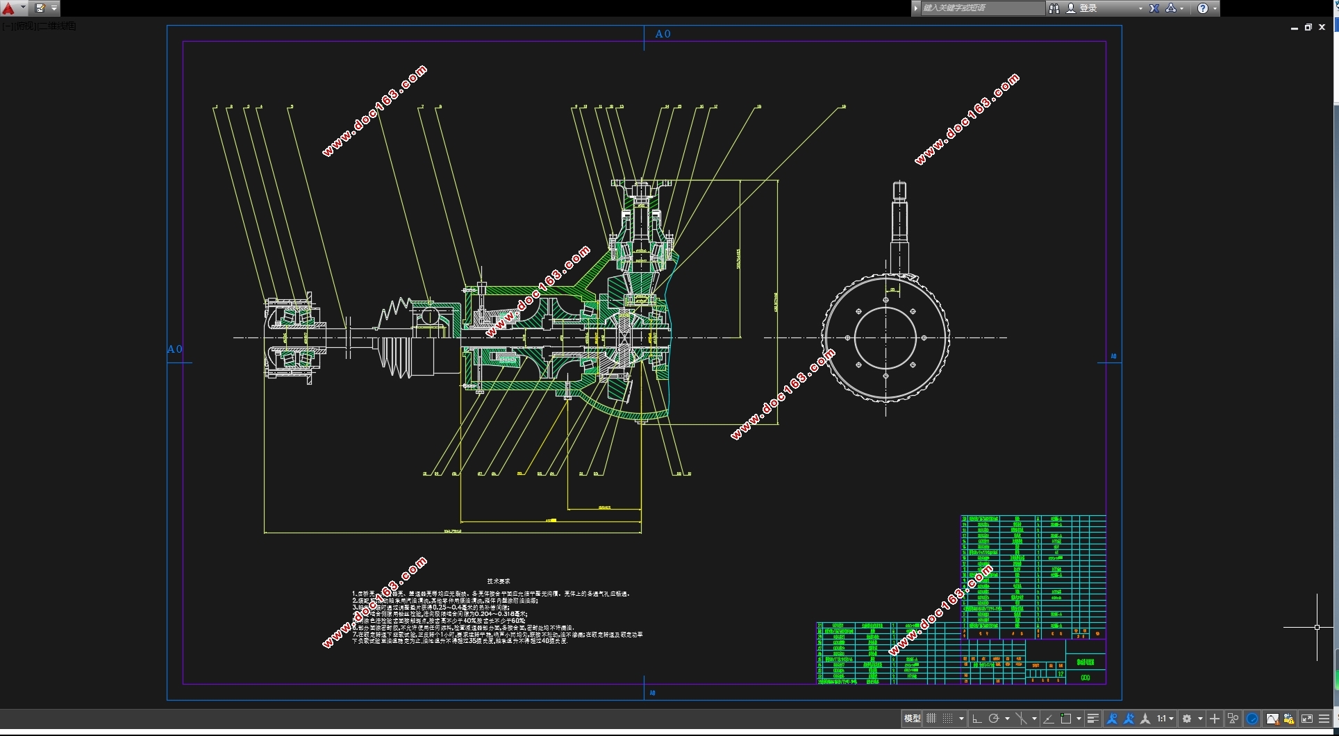
本设计是根据东风猛士EQ2050B车型,进行断开式驱动桥设计。设计内容包括主减速器、差速器、半轴和万向节的选型及其设计。设计结果通过Catia软件进行三维建模,并导出二维图,最后在AutoCAD中修改,制出符合要求的工程图。设计过程中,运用多学科知识严格设计,并完成校核。计算过程借助Matlab、excel等软件计算,提高计算效率。建模过程中,对齿轮、渐开线花键等零件进行参数化建模,以利于快速修改。最终完成具有以双曲面齿轮传动的单级减速器、气动牙嵌式的强制锁止式差速器和全浮式半轴的断开式驱动桥设计。本设计过程对汽车驱动桥的设计具有参考作用,是综合多学科知识进行汽车设计的尝试。
关键词:汽车驱动桥;主减速器;差速器;
Abstract
This paper is the design of independent suspension drive axle based on Dongfeng “Mengshi” high mobility off- road vehicle, whose code name is EQ2050B. The design includes final drive, differential and axle shaft .Design results was modeled by Catia and derived two-dimensional maps, and finally was modified in AutoCAD to meet the requirements of the engineering drawing. Through multidisciplinary knowledge, design strictly and check completely in the design process. Matlab,excel and other calculate software were used to improve the calculation efficiency .The parametric modeling process of Gears and involute splines is helpful to modification. Finally, the design of independent suspension drive axle is completed ,which includes a single final drive by hypoid gear drive, a pneumatic forced locking differential and a full-floating half axle drive .This design process has reference function to the design of automobile drive axle, it’s an attempt to combine multidisciplinary knowledge for automobile design.
Key words:automobile drive axle; final drive; differential;
[资料来源:http://doc163.com]
 [资料来源:http://Doc163.com]
目录
第1章 绪论 1
第2章 现有车型的基本参数及分析 2
第3章 主减速器的设计 3
3.1 主减速器的结构选型 3
3.1.1 主减速器齿轮的选型 3
3.1.2 主减速器齿轮的支承形式及布置方法 3
3.1.3 主减速器的减速形式 4
3.2 主减速器基本参数的选择与设计计算 5
3.2.1 主减速器传动比的确定 5
3.2.2 主减速器齿轮计算载荷的确定 6
3.2.3 主减速器基本参数的初步确定 8 [资料来源:https://www.doc163.com]
3.2.4 “格里森”制双曲面齿轮几何尺寸的计算 10
3.2.5 主减速器齿轮的强度校核 12
3.2.6 主减速器轴承的选型及校核 15
第4章 差速器的设计 20
4.1 汽车差速器的选型 20
4.2 差速器的设计计算 21
4.2.1 差速器齿轮基本参数的选择 21
4.2.2 差速器齿轮几何尺寸的计算 22
4.2.3 差速器齿轮的强度校核 23
第5章 车轮传动装置的设计 24
5.1 半轴的形式选择 24
5.2 半轴的设计 24
5.2.1 半轴计算载荷的确定 24
5.2.2 半轴的强度校核 25
5.2.3 半轴花键的设计及校核 25 [资料来源:Doc163.com]
5.3 万向节的选型及其设计 27
第6章 结论 28
参考文献 29
附录A 30
致谢 32
[资料来源:https://www.doc163.com]
上一篇:6×6混合动力汽车行驶及驱动系统设计(含CAD图,CATIA三维图)
下一篇:小型电动代步车制动系统设计(含CAD零件图装配图)(英文)
