某城市物流用轻型电动厢式货车驱动桥设计(含CAD零件图装配图)

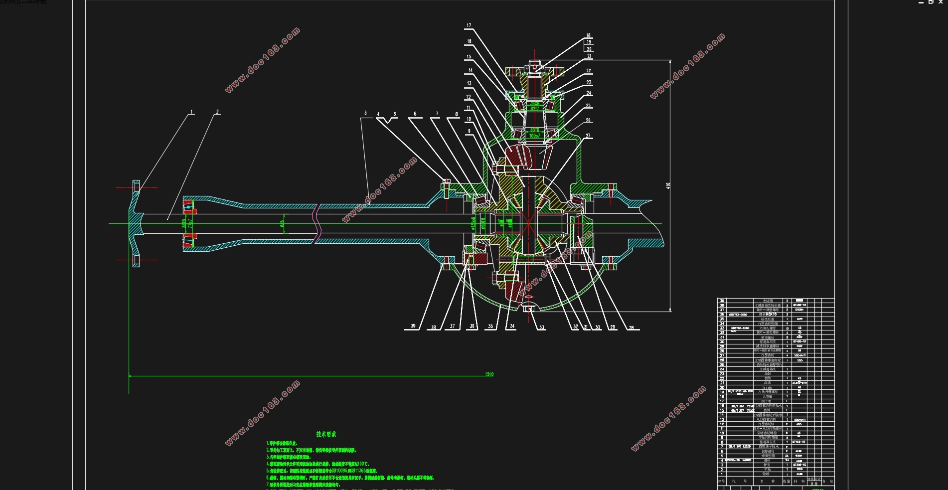
某城市物流用轻型电动厢式货车驱动桥设计(含CAD零件图装配图)(任务书,开题报告,论文说明书16500字,CAD图8张)
摘要
众所周知,任何一个运动的机械必须要具备动力源以及动力传递或转换装置,汽车也不例外。内燃机或者发电机作为动力源,不断输出能量,若要让这些能量转化成驱动车轮的转动并且能根据人类的要求表现出各种工况,需要设计处一个与之匹配的动力传递路径。本文着眼于汽车后续动力传递装置——驱动桥,承接变速器传递而来的动力,在驱动桥这一级进行详细的设计,实现动力传递的要求。结合现实生活中蓬勃发展的城市物流行业,从功能需求出发,基于传统的驱动桥设计方案的前提,给出在电力驱动下,驱动桥的设计解决方案。并且运用现代数字技术,在CATIA软件中对初步计算得来的尺寸进行直观显示,以避免不合常理的零件静态干涉和运动时的干涉。在该方案的细分步骤中,主减速器的作用是动力传输换向和增加一级传动比,使汽车有足够的扭矩驱动车轮;汽车在转弯时,在与前进速度垂直的直线上的左右车轮中,线速度总是不一样的,单靠简单的传动,无法实现这种功能,因此差速器的核心功能是实现与其同轴旋转的装置的角速度差异;汽车的动力传动最终是施加在车轮上的,因此还需要一个从差速器的车轮之间的过渡,这就需要半轴作为动力的传递。半轴通过轴承被驱动桥支撑,不仅如此,驱动桥还有着支承汽车重量的功用,任何集成的装置需要用壳体来密封,以避免与外界的接触损坏,除了包裹作用,壳体还兼顾动力传递,桥壳的刚度和强度对整个驱动桥的工况尤其是半轴的工作有重要的影响,驱动桥壳在曲面过渡处容易发生疲劳损坏,因此保证驱动桥壳的寿命是设计桥壳时必须考虑的问题,因此有必要对壳体进行有强度校核,以确保使用期间的绝对安全。 [来源:http://Doc163.com]
关键词:动力传递;驱动桥设计;CATIA建模;强度校核
Abstract
As we all know, any movement of the machine must have a power source and power transmission or conversion device, the car is no exception. The internal combustion engine or generator as the power source, constant output energy, to let these energies into the driving wheel rotation and according to the requirements of showing a variety of conditions, need to design a matching power transmission path. This paper focuses on the power transmission device of the vehicle, the drive axle, and the power transmission from the transmission, and carries on the detailed design in the drive axle. Combined with the real life of the city's booming logistics industry, from the functional requirements, based on the premise of the traditional design of the drive axle, given the power driven, the design of the drive bridge solutions. And the use of modern digital technology, in the CATIA software for the initial calculation of the size of the visual display, in order to avoid unreasonable parts of the static interference and interference in motion. In the segmentation step of the design of the main reducer is the role of power transmission, commutation and increase the level of transmission ratio, make the car have enough torque to drive the vehicle wheel; when cornering, the forward velocity and the vertical line on the left and right wheels, line speed is not always the same, only by simple transmission. To achieve this, so the core function is to achieve the angular velocity difference differential device and the coaxial rotation of power transmission; the final car is applied on the wheel, so it also needs a transition from the differential wheel, which requires half shaft as the power transmission, and between the axle and the wheel also the need for a universal transmission device, because the car in the beating process, the relative position of the wheel and the drive axle are constantly changing, you cannot directly use the hard connection, and to use the change to change To adapt to this special condition. There is a car driving axle bearing weight function, the need to use any integrated device casing to seal, to avoid damage to contact with the outside world, but also take into account the parcel, shell power transmission condition of bridge shell strength and stiffness of the drive axle especially half shaft work has an important influence on driving the bridge shell is prone to fatigue damage in the surface transition, so that the life of the drive axle housing is designed to be taken into account when the housing problem, it is necessary to have the casing strength check to ensure absolute safety during use.
[资料来源:http://doc163.com]
Key Words:Power transmission; Drive axle design; CATIA modeling; Strength check
[版权所有:http://DOC163.com]


目 录
摘要 I
Abstract II
第1章绪论 1
1.1 课题研究的背景及意义 1
1.2 汽车驱动桥国内外发展现状 2
1.3 本课题研究的主要内容和研究方法 3
第2章驱动桥的总体结构及整车参数 4
2.1 驱动桥的总体结构 4
2.2整车参数 5
第3章主减速器设计 7
3.1 主减速比的确定 7 [资料来源:http://Doc163.com]
3.2 主减速器的减速形式和支承方案 7
3.3 主减速器齿轮的尺寸计算 10
3.4 主减速器齿轮的强度校核 14
3.5 主减速器轴承的强度校核 16
3.6 主减速器齿轮的材料及热处理 20
第4章差速器设计 21
4.1 差速器结构形式选择 21
4.2 差速器齿轮的尺寸设计 21
4.3 差速器齿轮的强度校核 22
4.4 十字轴的设计与校核 24
第5章半轴和驱动桥壳设计 26
5.1 半轴的结构设计与校核 26
5.2 驱动桥壳的结构设计与校核 29
第6章结论 34
参考文献 36
致谢 37
[资料来源:www.doc163.com]
上一篇:轻型客车的平顺性研究(减震器设计)(含CAD图,CATIA三维图)
下一篇:五菱汽车后制动器设计(盘式制动器)(含CAD零件图装配图)
