
电动汽车框架车身设计及分析(含CAD图,CATIA三维图)
电动汽车框架车身设计及分析(含CAD图,CATIA三维图)(任务书,开题报告,文献摘要,论文说明书10000字,CAD图纸3张,CATIA三维图1张)
摘 要
汽车框架起着支撑整车,传递部分力的作用,是汽车的重要组成部分,因此车身框架的设计对整车的安全、可靠性十分关键。前些年,电动客车已出现在市场,代表有比亚迪K9等车型,因此本文计划以电动客车为设计对象对其进行车身框架设计。
首先对客车车身框架进行了选型,然后继续设计了左右侧围框架结构、顶盖框架结构、前、后围框架结构,最终建立了客车框架的三维模型。然后查阅同类车型的信息,对本文电动汽车进行了驱动桥设计计算,在通过计算校核之后,结果表示我们的设计满足要求。
最后通过ansys对客车框架的三维模型进行了有限元模态及强度仿真,仿真结果表明车架低阶频率都在3~25Hz之间,频率满足设计要求;车身框架最大应力值为141MPa,小于Q235屈服极限,框架设计满足强度要求。
关键词:汽车框架,设计,维模型,有限元模态及强度仿真
ABSTRACT
The automobile frame plays an important role in supporting the whole vehicle and transferring part of the force. Therefore, the design of the body frame is crucial to the safety and reliability of the whole vehicle. In the previous years, the electric bus has appeared in the market, representing the BYD K9 and other models, so this article plans to design the car body frame with the electric bus as the design object.
[来源:http://Doc163.com]
First, the frame of the bus body is selected, then the left and right circumference skeleton structure, the top cover skeleton structure, the front and rear frame structure are continued, and the three-dimensional model of the bus frame is finally established. Then consult the information of the same type of vehicle, carry on the design and calculation of the drive bridge of the electric vehicle, and check it. The results show that the drive bridge meets the design requirements.
Finally, the finite element modal and strength simulation of the three dimensional model of the bus frame is carried out. The simulation results show that the low order frequency of the frame is between 3 and 25Hz, and the frequency satisfies the design requirements; the maximum stress value of the body frame is 141MPa, less than the Q235 yield limit, and the frame design satisfies the strength requirement.
Key words: vehicle frame, design, dimension model, finite element mode and intensity simulation
[资料来源:www.doc163.com]
本文的设计是从客车出发,打算设计一款中档的旅游车。
长度初步确定为8米,发动机的布置形式选择为发动机后布置。车身结构确定为是半承载式车身结构。车的内部,将空间划分为两个部分:
上层的空间是行李的存放位置,下层的空间则留给乘客。客车的前部车门选择气动形式的向外摆出的乘客门,为节省空间选择单扇车门。对于车身地板本文将地板设计为高地板的结构,地板的中部则为乘客站立以及走动的区域。
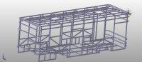
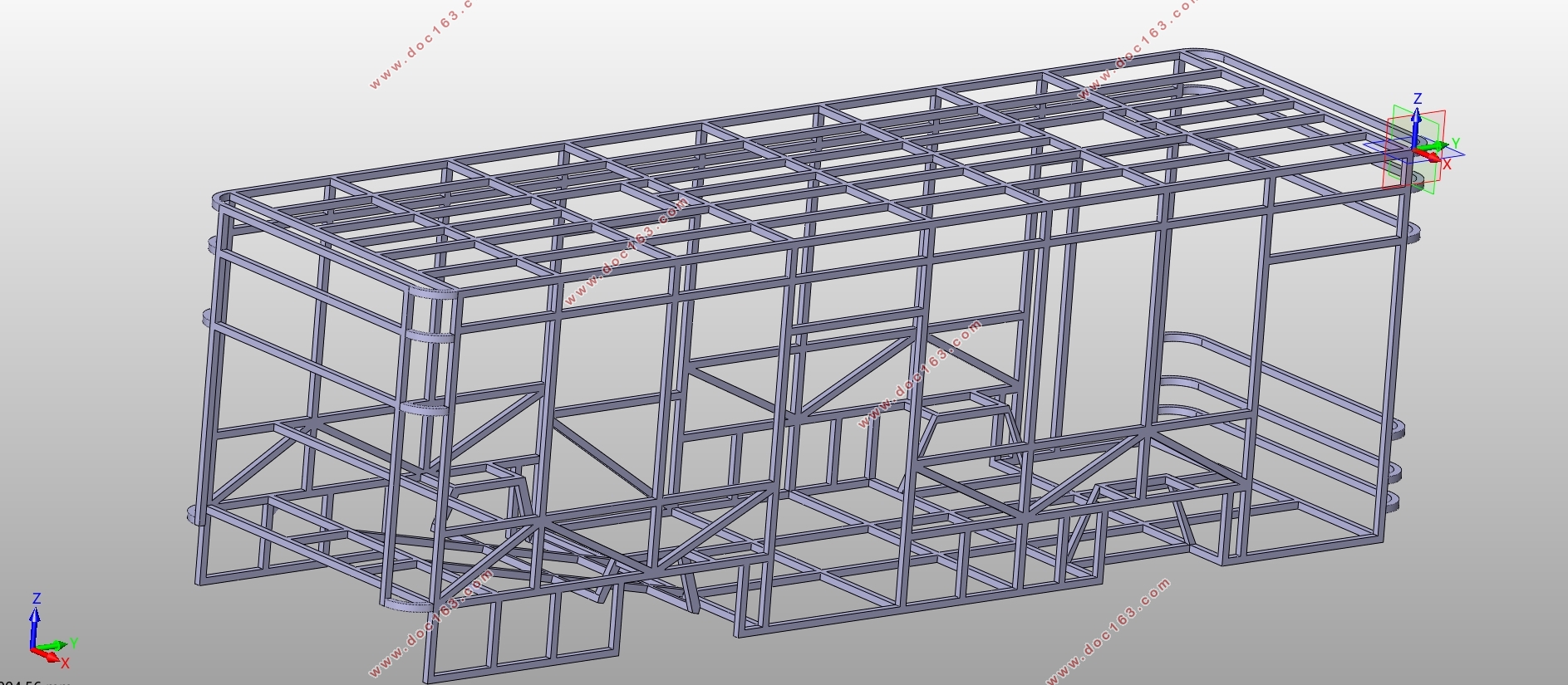
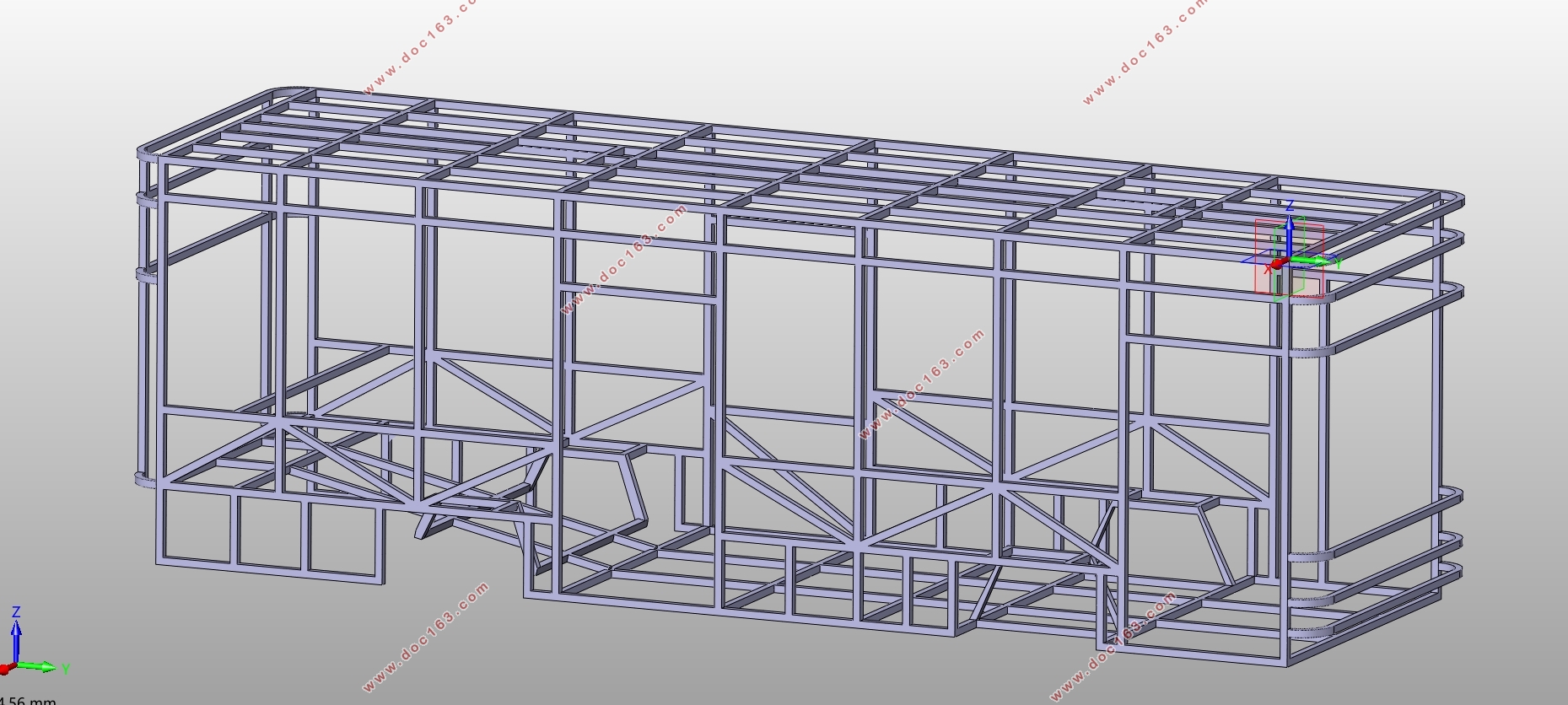
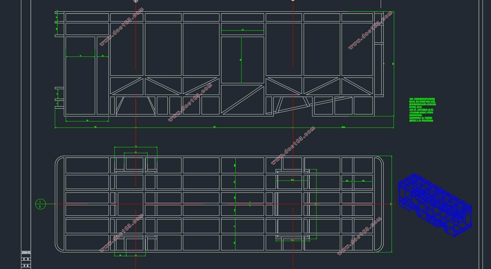
本文设计的车身框架结构三维图如下。
座椅布置行使如下:
形式设计为31+1+1模式,靠窗部分布置两列座椅,在车尾的部分布置一排可以坐下5人的座椅。左右两侧的座椅是双人座椅。在排数上,左边6排,右边7排。再加上前侧司机以及导游,一共33个座位。
[来源:http://Doc163.com]
 [资料来源:http://Doc163.com]
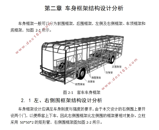

目录
第一章 车身框架选型 1
1.1客车车身分类方法 1
1.1.1按用途分类 1
1.2.2按承载形式分 2
第二章 车身框架结构设计分析 5
2. 1 左、右侧围框架结构设计分析 5
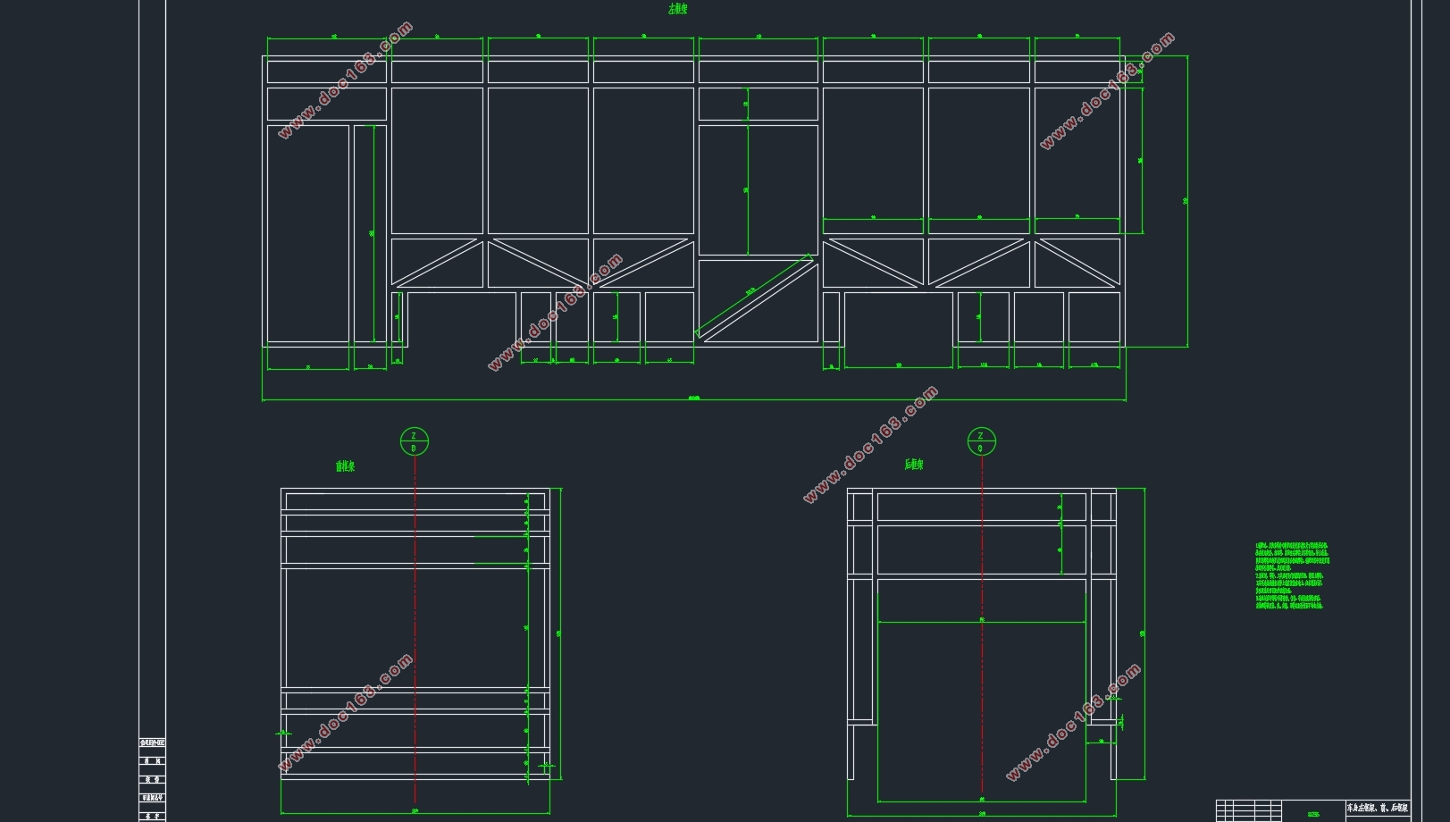
2.2 顶盖框架结构分析 6
2.3 前、后框架结构分析 7
2.4框架三维模型 8
第三章 驱动桥设计计算 9
3.1驱动桥选型 9
3.2 主减速器传动比的计算 11
3.2.1 轮胎参数的确定 12
3.2.2主减速比的确定 12
3.3主减速器锥齿轮设计 13
3.3.1 计算从动锥齿轮转矩 13
3.3.2主减速器锥齿轮的主要参数选择 13
3.4主减速锥齿轮的强度校核 15
3.4.1齿轮弯曲强度校核 15
3.4.2齿面接触强度校核 15
3.5差速器的设计与计算 16
3.5.1 差速器齿轮设计 16
3.5.2差速器齿轮的几何尺寸计算表 19
第四章 车身框架有限元分析 21 [资料来源:http://Doc163.com]
4.1框架车身模态分析 21
4.1.1车架的自由模态分析以及有限元模型建立 21
4.2框架车身强度分析 24
4.2.1边界条件设置 24
4.2.2强度计算结果 25
总结与展望
参考文献
致谢 [资料来源:http://www.doc163.com]
上一篇:微型两座电动轿车车身造型设计及空气动力学分析(含CAD图,IGS三维图)
下一篇:纯电动汽车制动系统设计(含CAD零件装配图,SolidWorks三维图)(英文版)