
重型牵引车车架的总体设计(含CAD零件图装配图,CATIA三维图)
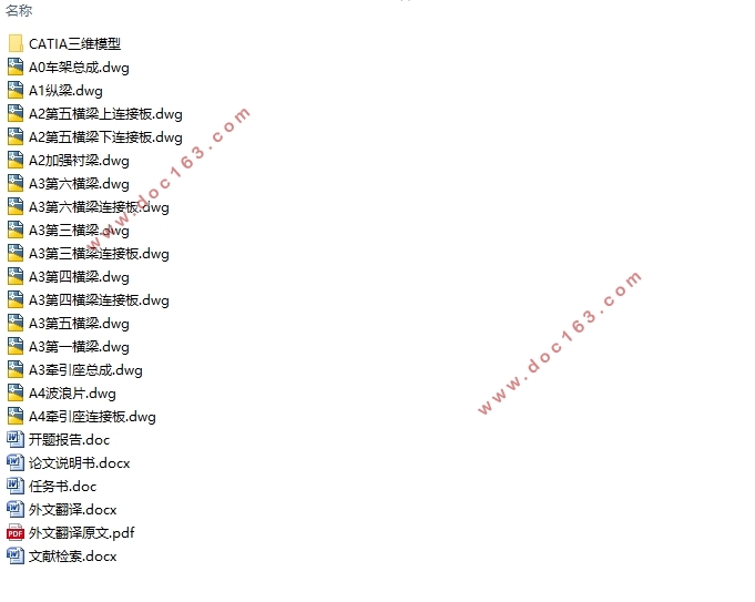
重型牵引车车架的总体设计(含CAD零件图装配图,CATIA三维图)(任务书,开题报告,文献摘要,外文翻译,论文说明书18000字,CAD图16张,CATIA三维图)
摘 要
本文首先讨论了牵引车在国内发展的形势,介绍了传统设计方法逐步改进为现代化设计方法的研究过程,提出了利用现代化设计方法设计重型牵引车车架,以避免某些车型出现的车架裂纹乃至断裂的设计目的,主要进行车架的总体设计,强度校核,三维模型建立,有限元及模态分析。
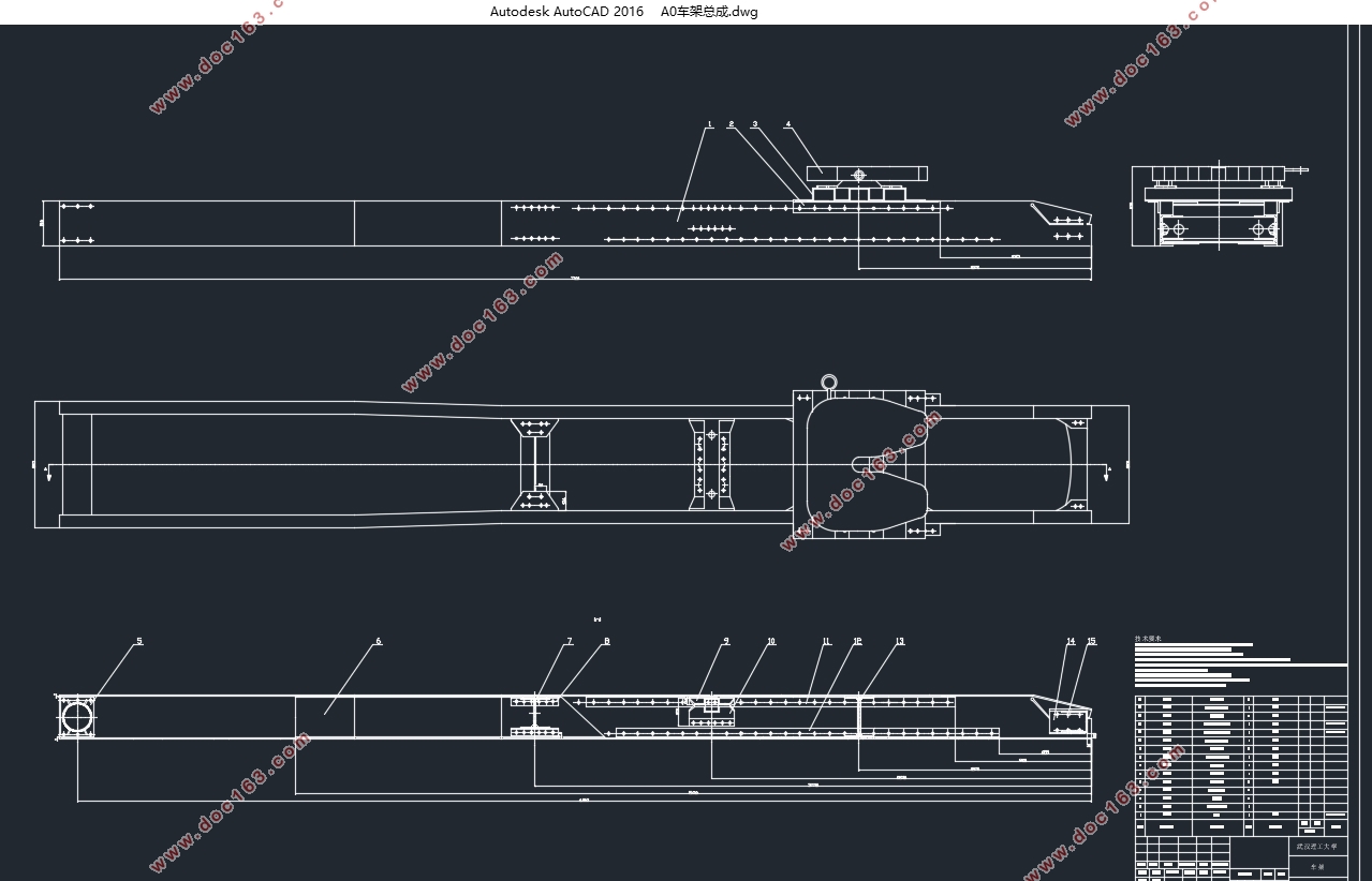
文章针对限重49t的6×4型半挂牵引车进行讨论,选定发动机功率,轴距等牵引车参数。根据车架设计的设计要求和设计原则,选定车架总体形式,纵横梁参数及连接方式。通过CATIA软件建立车架总成的三维模型,完成车架的初步设计。
对设计的车架首先进行满载匀速工况、满载弯曲工况和满载制动工况的多刚体静力学分析,计算结果可以预估车架总成满足使用设计要求。然后建立有限元模型,利用ANSYS软件对车架总成的几种典型工况进行有限元分析,得出数值结果证明车架满足设计要求。最后,将有限元计算结果与多刚体计算结果进行对比,验证两种分析方式的正确性。
为减少或避免车架总成与来自路面及发动机等传递的激励发生共振,利用ANSYS对车架总成做模态分析,计算得到车架总成的固有频率与振型,与来自地面及发动机激励频率对比,进行改进车架结构。
此次课题为同类重型牵引车车架在设计、分析和优化改进方面提供了参考意义。
关键词:车架纵梁横梁有限元 模态
Abstract
This paper first discusses the development of tractor in the domestic situation, introduced the traditional design method to gradually improve the modern design method of research process, proposed the use of modern design method design of heavy tractor frame to avoid some models of the frame cracks And even the purpose of the design of the fracture, the main frame of the overall design, strength check, three-dimensional model, finite element and modal analysis.
This paper discusses the 6 × 4 type semi - trailer tractors with weight 49t, and selects the parameters such as engine power and wheelbase. According to the design requirements of the frame design, design principles, the overall form of the selected frame, vertical and horizontal beam parameters and connection. The three - dimensional model of frame assembly is established by CATIA software , To complete the initial design of the frame. [资料来源:https://www.doc163.com]
The design of the frame first full load uniform conditions, full load bending conditions and full load braking conditions of the multi-rigid body static analysis, the calculation results can be expected to meet the use of frame assembly design requirements. Then, the finite element model is established, and several typical working conditions of the frame assembly are analyzed by ANSYS software. The numerical results show that the frame meets the design requirements. Finally, the finite element calculation results are compared with the results of multi-rigid body calculation to verify the correctness of the two analysis methods.
In order to reduce or avoid the frame assembly and from the road and the engine and other transmission of the resonance occurred, the use of ANSYS frame to do modal analysis to calculate the frame assembly of the natural frequency and vibration, and from the ground and the engine Excitation frequency comparison, to improve the frame structure.
This topic is a reference for the design, analysis and optimization of the same heavy-duty tractor frame. [资料来源:http://Doc163.com]
Key words:FrameStringerBeam Finite eleme Modal
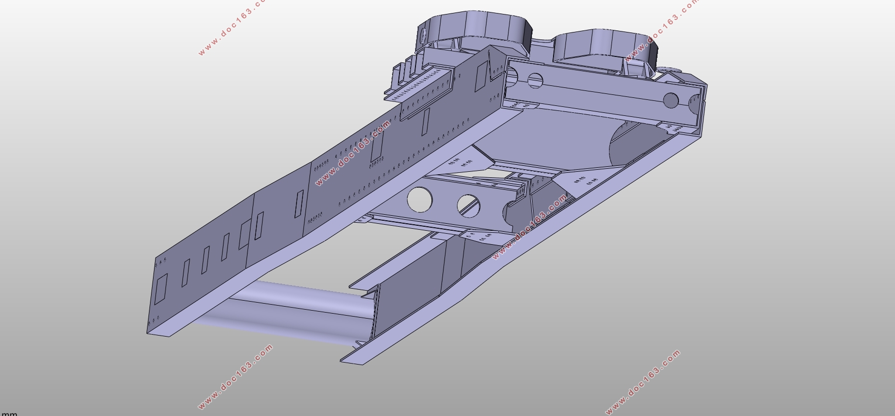
结构总体设计
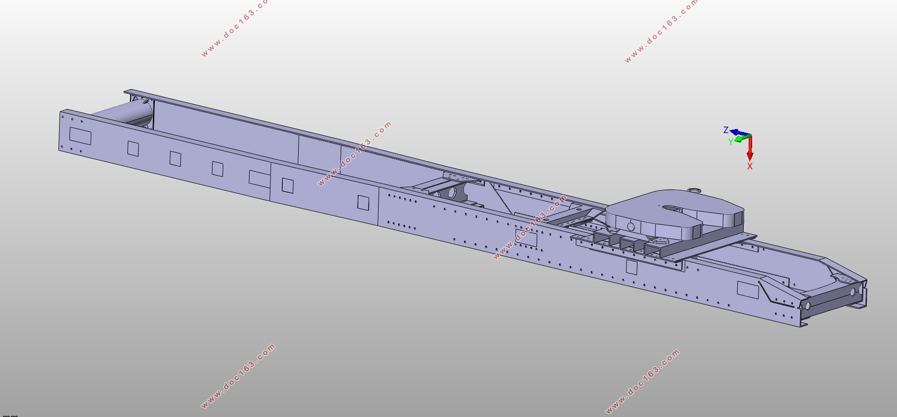
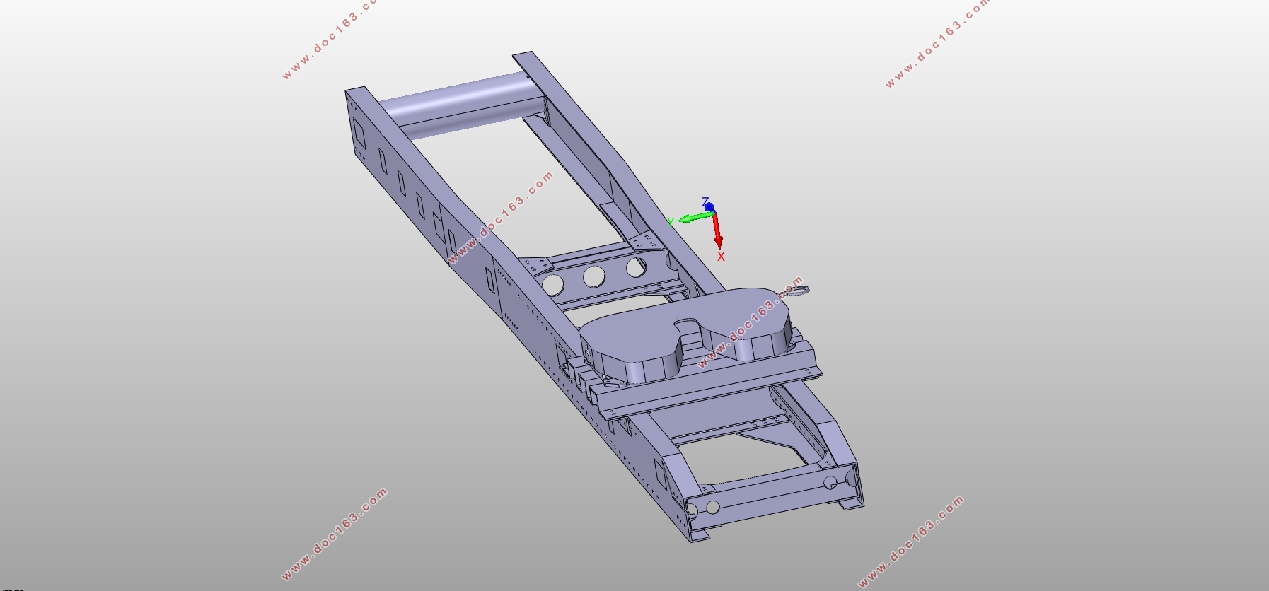
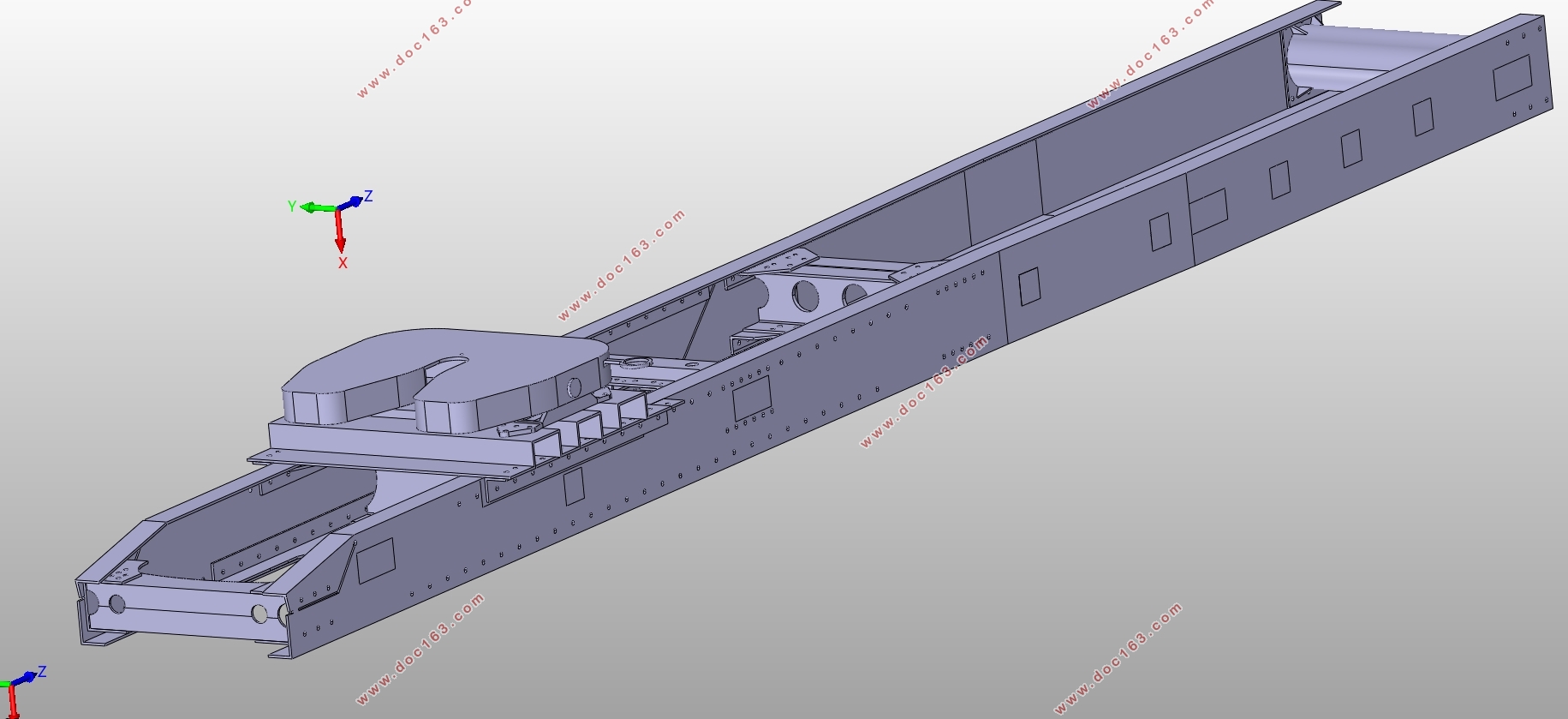
针对牵引车来讲,车架一般选用梯形结构,即边梁式车架,主要有直通粱、前窄后宽、前宽后窄等几种形式。直通粱相较来说,结构简单,加工成本低,便于系列化设计。前窄后宽式车架保证了牵引车足够的转向空间。前宽后窄式车架可以搭载大功率发动机和宽体驾驶室,符合牵引车发展的趋势;同时,便于钢板弹簧的布置。
上一章中选用的发动机功率为350kw/460马力,尺寸较大(参照附录B)。为实现其合理安装使用,同时结合市场成熟车型,车架形式选择为前宽后窄形式。车架前部宽度为860mm,后部宽度为800mm,为避免应力集中导致车架出现疲劳损伤,车架前部2000mm处由860mm渐变为800mm,同时镶嵌6mm厚槽型衬梁。
在车架整体结构中,驾驶室前悬置与转向系统安装位置为车架的前部,这就要求车架前部刚性较大避免发生疲劳开裂。后轴轴组处需要有足够的刚性约束,以保证牵引车对半挂车有足够的承载能力。车架后悬区段属于弯曲扭转组合变形区,应具有适当的柔性。不同变形区段过渡需采用渐变结构以避免应力集中。
综上所述,在车架设计时,车架前后两部分应保证较大刚性,中间部分可以存在适当的可回复扭曲和挠曲变形。选取车架扭转刚度时,应避免变形过大而造成车辆横摆严重,行驶中的最大扭角约为每秒轴距1°。车架垂直弯曲刚度应保证满载状态下弯曲挠度在10mm内[27]。 [资料来源:https://www.doc163.com]
[资料来源:Doc163.com]
[版权所有:http://DOC163.com]
目录
第1章绪论 1
1.1 课题的提出 1
1.2 课题的目的及意义 1
1.3 国内外研究现状 2
1.4 主要研究内容 3
第2章牵引车参数确定 5
2.1 牵引车类型选取 5
2.2 最大功率选取 5
2.3 轴距L选取 6
2.4 轮距B选取 6
2.5 轮胎尺寸选取 6
第3章车架总体设计确定 7 [版权所有:http://DOC163.com]
3.1 车架设计要求 7
3.2 车架设计原则 7
3.3 结构总体设计 8
3.4 纵梁设计 8
3.4.1 截面形状 8
3.4.2 截面尺寸 9
3.4.3 纵梁长度 10
3.4.4 纵梁材料 10
3.5 横梁设计 11
3.5.1 截面形状 11
3.5.2 布置方案 12
3.5.3 横梁布置位置 12
3.5.4 横梁材料 12
3.6 横纵梁连接 12
3.6.1 横梁与纵梁的连接方式 12
3.6.2 横梁与纵梁的连接方法 13
3.6.3 横梁与纵梁连接确定 13
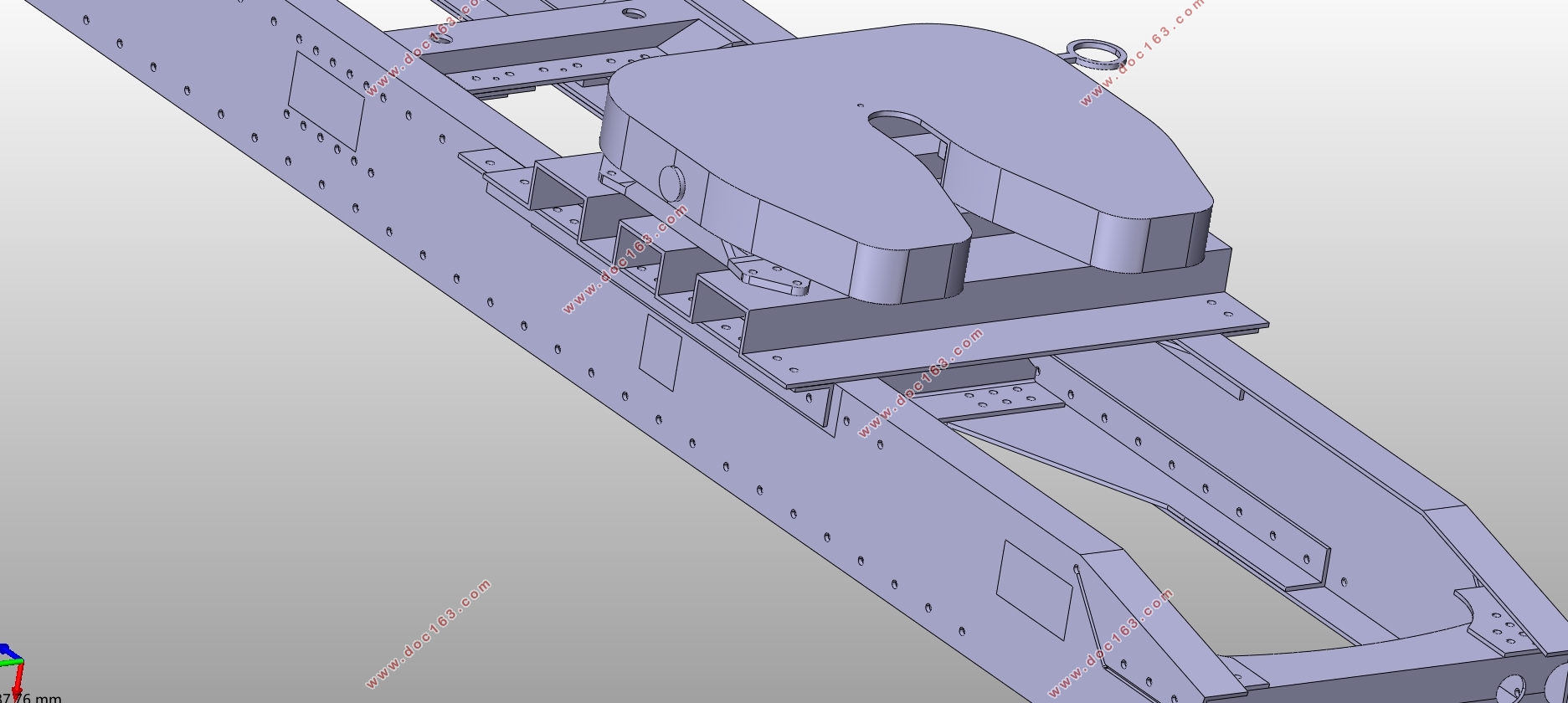
3.7 牵引座选取 13
第4章三维模型的建立 14
4.1 软件介绍 14
4.2 纵梁模型建立 14
4.3 横梁模型建立 14
4.4 连接板模型建立 16 [来源:http://Doc163.com]
4.5 牵引座模型建立 17
4.6 车架模型建立 17
第5章多工况设计计算 18
5.1 满载匀速行驶工况 18
5.2 满载弯曲工况 21
5.3 满载制动工况 21
5.4 静力学计算结论 23
第6章多工况数值分析 24
6.1 满载弯曲工况 24
6.2 满载制动工况 25
6.3 满载扭转工况 26
6.4 满载转弯工况 27
6.5 数值分析结论 28
第7章模态分析 29
第8章总结与展望 32
8.1 总结 32
8.2 工作展望 32
参考文献 33
附录A 35
附录B 36
附录C 36
附录D 36
附录E 37
致谢 38
上一篇:六轮越野无人车驱动系统和整车布置设计(含CAD零件图装配图,SolidWorks三维