东风AX7盘式制动系统设计(含CAD零件图装配图,CATIA三维图)

东风AX7盘式制动系统设计(含CAD零件图装配图,CATIA三维图)(任务书,开题报告,文献摘要,外文翻译,论文说明书15000字,CAD图5张,CATIA三维图)
摘 要
制动系统主要是用于确保汽车的行车安全的装置,相关的法规和制造标准对制动器的设计提出了细致的要求,本文依据这些设计标准和本次毕业设计的任务书中的要求,主要对东风AX7汽车的制动器进行了设计。
总结制动器的作用,参考其设计要点,在各项参数中选择最合适的参数来进行设计计算是本次设计的出发点。同时本文还对各种不同型式的制动器进行的对比分析,在综合考虑了制动器的性能,制造难度和生产成本等问题后采取了择优选择,以此来最终确定前后轮制动器的形式。本文对制动器的选型,设计取值和计算的内容进行了较为详细的说明。
本文还利用ABAQUS软件对制动器的制动过程的数值模拟分析,得出了相应的结论。
关键词:盘式制动器;制动盘;制动钳;模拟分析
Abstract
Braking system is mainly used to ensure that the car driving safety devices, the relevant laws and regulations and manufacturing standards on the design of the brake made a detailed request, this paper based on these design standards and the graduation design task book requirements, Dongfeng AX7 car brakes were designed.
Summarize the role of the brake, with reference to its design points, in the parameters of the most appropriate parameters to design and design is the starting point for this design. At the same time, this paper also makes a comparative selection on the brake of various types of brakes, and takes the choice of brake after considering the performance of the brake, the difficulty of manufacturing and the production cost, so as to finally determine the form of the front and rear wheel brakes. In this paper, the selection of the brake, design values and calculation of the contents of a more detailed description.
In this paper, ABAQUS software is used to simulate the braking process of the brake, and the result are drawn.
Key words: disc brake; brake disc; brake caliper; simulation analysis
东风AX7盘式制动系设计:
尺寸参数:长4690mm,宽1850mm,高1727mm,轴距2712mm,前轮距1585mm,后轮距1585mm,质心高度560mm
质量参数:整车整备质量1542kg,总质量1892kg,前后轴载荷(满载前55%后45%)
[资料来源:http://www.doc163.com]
性能参数:发动机排量1.4L,最大功率103Kw,最大转矩196N•m,最高车速185Km/h,轮胎滚动半径326mm
[资料来源:http://www.doc163.com]
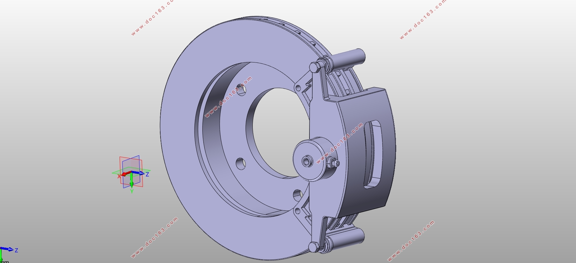
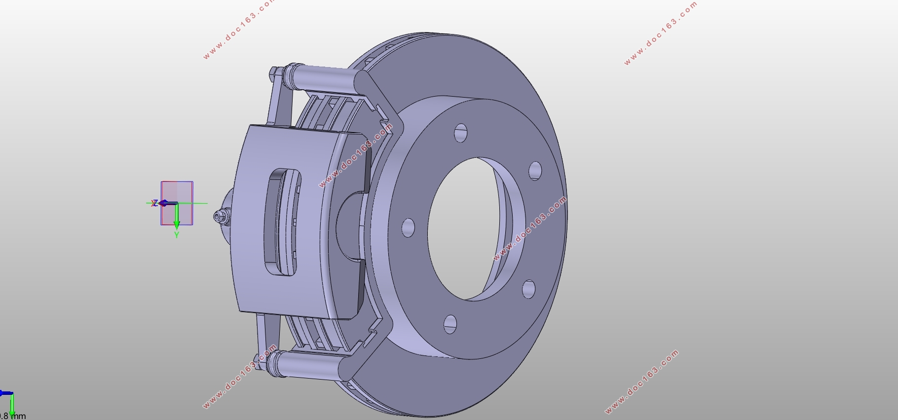
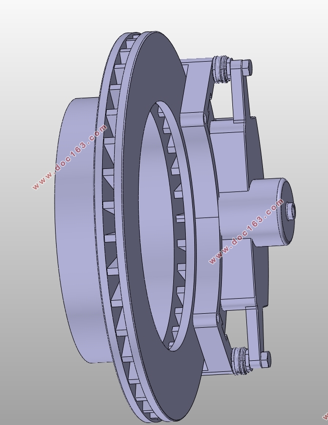
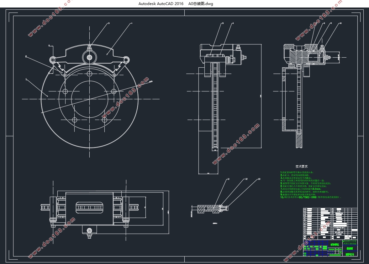
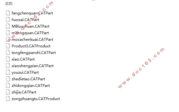 [资料来源:http://Doc163.com]
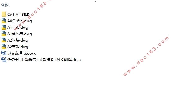
目录
摘要 I
Abstract II
第1章绪论 1
1.1 制动系统的基本概念 1
1.2 制动系统发展史及研究现状 1
1.2.1制动控制系统的历史 1
1.2.2制动控制系统的现状 2
1.3 课题主要内容 3
1.4 课题研究方案 4
1.5 本章小结 4
第2章制动器方案选择 5
2.1方案选择的依据 5
2.2方案的选定 5
2.2.1制动器选择 5
2.2.2前、后轮盘式制动器选型 6
2.3本章小结 9
第3章制动器参数的设计和计算 10
[资料来源:http://www.doc163.com]
3.1制动盘直径 10
3.2制动盘厚度 10
3.3摩擦衬块的内半径R1和外半径R2 10
3.4摩擦衬块面积 11
3.5制动轮缸压强 11
3.6摩擦力的计算和摩擦系数的验算 11
3.7制动力矩的计算和验算 12
3.8驻车制动计算 13
3.9本章小结 14
第4章制动器的主要零部件的结构设计 16
4.1制动盘 16
4.2制动钳 16
4.3制动块 16
4.4摩擦材料 17
4.5制动器间隙的调整方法及相应机构 17
4.6本章小结 17
第5章制动过程的数值模拟 18
5.1模拟的操作过程及结果 18
5.2本章小结 27
第6章结论 28
参考文献 29
致谢 30
附录A 31 [资料来源:http://www.doc163.com]
附录B 33 [资料来源:http://Doc163.com]
上一篇:轿车五档FR式手动变速箱设计(含CAD零件图装配图)
下一篇:某中型东风载货车后轮制动系设计(含CAD零件图装配图)
