LG1091货车驱动桥设计(含CAD零件图装配图,STP三维图)

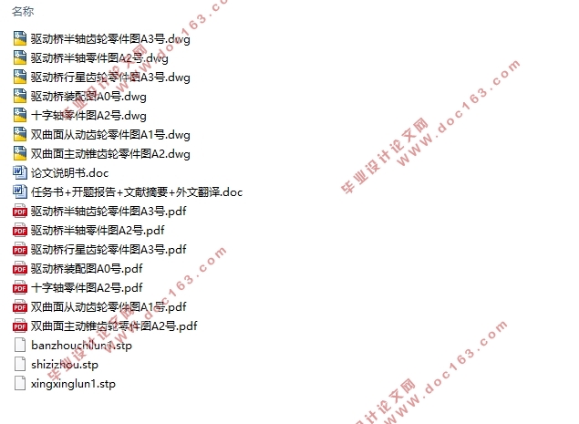
LG1091货车驱动桥设计(含CAD零件图装配图,STP三维图)(任务书,开题报告,外文翻译,文献摘要,论文说明书9000字,CAD图7张,STP三维图)
摘 要
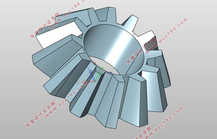
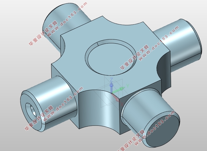
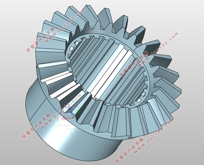
本次毕业设计首先通过查阅大量资料了解了驱动桥是由哪些零件结构组成的。然后再对各部分结构形式进行分析,从而得出了总体的一个设计结构方案:整体式驱动桥搭配单级主减速器,主减速器采用双曲面齿轮,以结构相对简单的普通对称式圆锥行星齿轮差速器作为主减速器结构形式,另外加上结构设计相对成熟的全浮式半轴,桥壳从经济成本出发选用铸造整体式桥壳。整个毕业设计编写过程中,做到了以上零部件或者总成的数据选取,校核及AUTOCAD工程图的画制。
关键词:铸造桥壳;设计;工程图;普通对称式差速器;核算
ABSTRACT
The graduation project first learned about the components of the drive axle by consulting a large amount of data. Then analyze the structure of each part, and then get a total design of the structure of the program: integrated drive axle with a single-stage main reducer, the main reducer using a hyperboloid gear, the structure is relatively simple ordinary symmetrical cone planet The gear differential is used as the final decelerator structure form, plus a full-fledged full-floating axle shaft with structural design, and the axle housing is selected from the economic cost to cast the integral axle housing. During the preparation of the entire graduation design, the selection of the above components or assembly data, the verification and the drawing of the AUTOCAD drawings were completed..
[资料来源:http://Doc163.com]
Key words: Cast Axle Housing; Design; Engineering Drawings; Common Symmetrical Differentials;
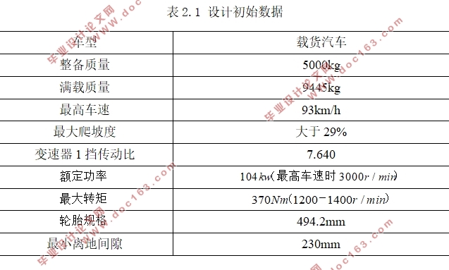
设计初始数据
车型 载货汽车
整备质量 5000kg
满载质量 9445kg
最高车速 93km/h
最大爬坡度 大于29%
变速器1挡传动比 7.640
轮胎规格 494.2mm
最小离地间隙 230mm

[资料来源:http://Doc163.com]
目 录
摘 要 I
ABSTRACT II
第1章 绪 论 1
1.1 研究背景 1
1.2 驱动桥设计意义 1
1.3 本设计研究内容 1
第2章 驱动桥总体布置 2
2.1 驱动桥总体布置 2
2.2 设计要求 2
2.3本章小结 2
第3章 主减速器计算 3
3.1 主减速器参数选定 3
3.1.1 主减速比i0的选定 3
3.1.2 主减速器计算载荷计算 3
3.1.3 主减速器参数选定 3
3.2 主减速器轴承的载荷计算 7
3.2.1 锥齿轮齿面上的作用力 7
[资料来源:https://www.doc163.com]
3.2.2 锥齿轮轴承及相关计算数据 8
3.3本章小结 10
第4章 差速器计算 11
4.1 普通圆锥对称式行星齿轮差速器的工作原理 11
4.2 普通圆锥对称式行星齿轮差速器的构成 11
4.3 普通圆锥对称式行星齿轮差速器的参数选取及验核 11
4.3.1 差速器齿轮的基本参数的选取 11
4.3.2 普通圆锥对称式差速器齿轮其余构成参数的数据列表 12
4.3.3 普通圆锥对称式差速器直齿锥齿轮强度校核 14
4.4本章小结 15
第5章 驱动半轴的计算 17
5.1 全浮式半轴计算载荷验算 17
5.2 全浮式半轴直径的初步选择 17
5.3 全浮式半轴的强度验算 17
5.4 半轴端部花键头基本参数的选定以及强度计算 18
5.4.1 半轴花键基本参数的选定 18
5.4.2 半轴花键的强度计算 18
5.5本章小结 19 [资料来源:www.doc163.com]
第6章 驱动桥桥壳的计算 20
6.1 驱动桥桥壳设计要求 20
6.2 桥壳的受力分析及强度计算 20
6.2.1 汽车以最大牵引力行驶时的桥壳强度计算 20
6.2.2 汽车紧急制动时的桥壳强度计算 20
6.2.3 汽车在不平路面冲击载荷作用下桥壳的强度计算 21
6.2.4 桥壳的静弯曲应力计算 21
6.3本章小结 21
致谢 27
参考文献 24
附录 25 [资料来源:www.doc163.com]
上一篇:驻车制动器在线装调设备系统设计(含CAD零件图装配图,CATIA三维图)
下一篇:东风风神AX1.5L汽车驱动桥设计(含CAD零件图装配图,SolidWorks三维图)
