紧凑型SUV转向系统设计(含CAD零件装配图)
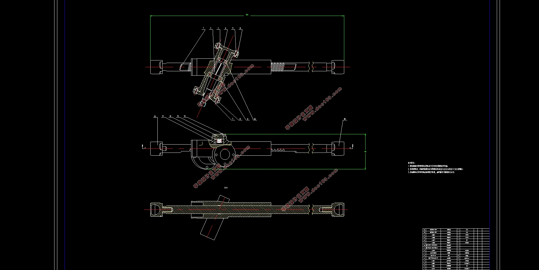
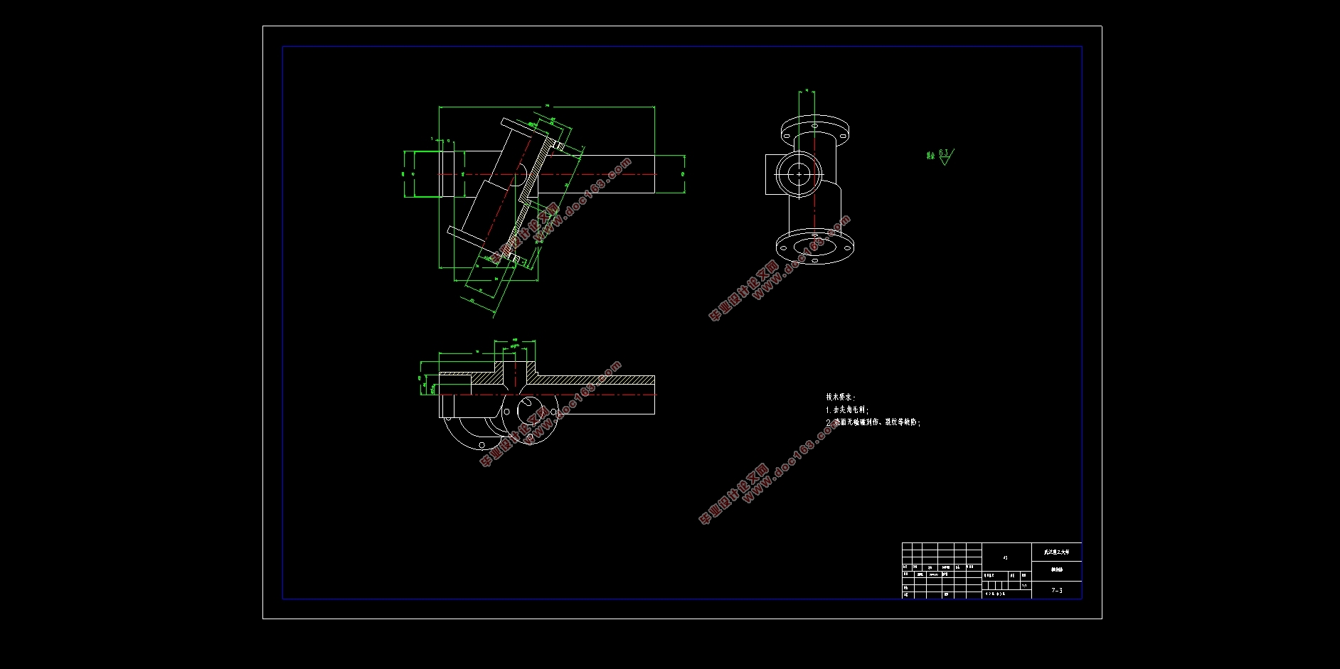
紧凑型SUV转向系统设计(含CAD零件装配图)(任务书,开题报告,文献摘要,外文翻译,论文说明书13000字,CAD图7张)
摘要
本文根据传统的转向系统设计方法,详细研究了紧凑型SUV的转向系统设计方法,提出了较为可行的技术方案,并根据这一方案进行设计、计算、校核、绘图。在设计过程中,查阅搜集了转向系统的基本结构原理以及发展现状,结合《汽车设计》、《汽车构造》等专业课知识,对转向器进行选型,设计斜齿轮轴、斜齿齿条等各主要部件结构参数,并对其进行强度校核。初步设计转向梯形机构,并利用MATLAB强大的运算功能以及简单的程序语法绘制直观的曲线图对其进行校验。同时对转向操纵机构以及转向传动机构的设计方法进行简要的整理。最后,根据设计参数,分别运用CATIA以及AutoCAD完成齿轮齿条式转向器的三维建模以及二维图纸绘制。本次毕业设计不仅丰富了我的专业知识,并且,让我对汽车零部件设计的流程及规范有了更深刻的认识。 [资料来源:www.doc163.com]
关键词:汽车 转向系统 齿轮齿条 转向梯形
Abstract
In this paper, according to the traditional steering system design method, the steering system design method of compact SUV is studied in detail, and a feasible technical solution is put forward. This article designs, calculates, checks and draws according to this scheme. In the design process, I combined the basic structural principles,the development status of the steering system and the professional knowledge of "Automotive Design" and "Automotive Construction" to select the steering gear and design the helical gear shaft and the helical gear rack. The structural parameters of the main components’ strength are checked. I designed the steering geometry and verified it through drawing intuitive graphs with MATLAB's powerful computational functions and simple program syntax. At the same time, the design methods of the steering operating mechanism and transmission mechanism are briefly arranged. Finally, according to the design parameters, I used CATIA and AutoCAD to complete the 3D modeling and 2D drawing of the rack-and-pinion steering. This graduation design not only enriched my professional knowledge, but also gave me a deeper understanding of the process and specifications of automotive parts design. [资料来源:http://www.doc163.com]
Keywords:Automotive Steering system Rack-and-pinion steering Steering geometry
[版权所有:http://DOC163.com]
 [资料来源:Doc163.com]

目 录
第1章绪论 1
1.1 汽车转向系统概述 1
1.1.1 转向系统组成及分类 1
1.1.2 转向系统功用 2
1.1.3 转向系统设计要求 3
1.2 国内外转向系统发展现状 3
1.3 设计基本内容 4
1.3.1 基本内容 4
1.3.2技术方案 5
第2章转向器的选型及结构设计 6
2.1 转向器的选型 6
2.2 转向器的基本参数设计 6
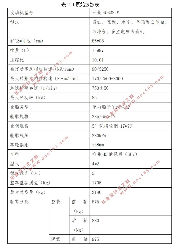
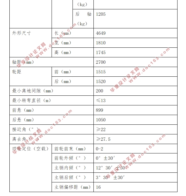
2.2.1 已知设计参数 6
2.2.2 齿轮基本参数的确定 8
2.2.3 转向系计算载荷的确定 8
2.2.4 小齿轮设计计算 10
2.2.5 小齿轮强度校核 12
[版权所有:http://DOC163.com]
2.2.6 齿轮轴结构设计 14
2.2.7 齿轮轴强度校核 15
2.2.8 齿条设计计算 19
2.2.9 齿轮齿条设计参数小结 20
第3章转向梯形机构的设计 22
3.1 转向梯形机构概述 22
3.2 断开式转向梯形机构设计 22
3.3 整体式转向梯形设计实例 23
3.3.1 整体式转向梯形特性分析 23
3.3.2转向梯形机构初步设计 24
3.3.3转向梯形机构设计校核 28
第4章转向操纵机构的设计 32
4.1 转向操纵机构概述 32
4.2 转向盘的布置及尺寸选择 32
4.3 转向轴的防伤安全措施 32
第5章转向拉杆及前束调整机构的设计 35
5.1 转向拉杆及球销设计 35
5.2 前束调整机构设计 35
第6章基于CATIA的齿轮齿条式转向器三维建模 36
6.1 CATIA软件简介 36 [资料来源:http://doc163.com]
6.2 齿轮齿条转向器的各部件建模 36
6.2.1 齿轮轴的三维建模 36
6.2.2 齿条的三维建模 38
6.2.3 转向器壳体的三维建模 39
6.2.4 齿轮齿条式转向器总装 40
第7章结论 41
参考文献 43
附录A 基于MATLAB的转向梯形机构校核程序 44
致谢 45
[资料来源:http://www.doc163.com]
上一篇:智能小车行驶系统设计(含CAD零件装配图,CATIA三维图)
下一篇:无人驾驶电动车悬架系统设计(含CAD零件装配图,CATIA三维图)
