
紧凑型轿车转向系统(电动助力)设计(含CAD图,CATIA三维图)
紧凑型轿车转向系统(电动助力)设计(含CAD图,CATIA三维图)(任务书,开题报告,外文翻译,论文说明书15400字,CAD图5张,CATIA三维图)
摘要
爱丽舍7164型轿车是东风神龙公司生产的一款紧凑型轿车,其转向系统采用的是液压助力转向系统。近年来,由于电动助力转向系统的不断发展、技术不断成熟,当下已有许多轿车配备该系统。相比液压助力转向系统,EPS摒弃了液压油缸、液压阀等部件,采用电动机与减速机构直接对转向进行助力,结构简单、紧凑,因此该系统的研究也成了各大厂商的热门任务之一。EPS的应用前景不可估量。
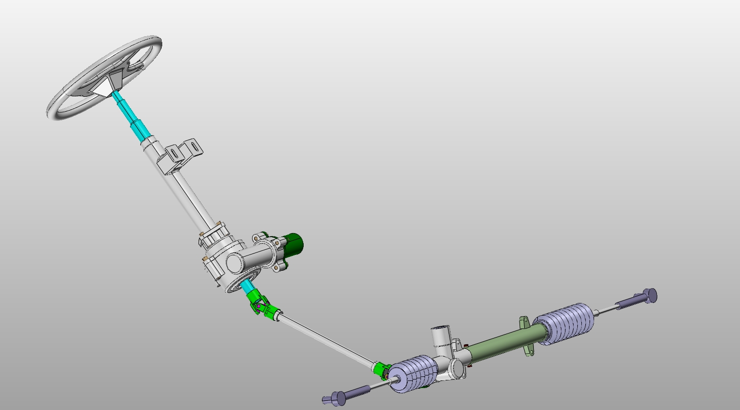
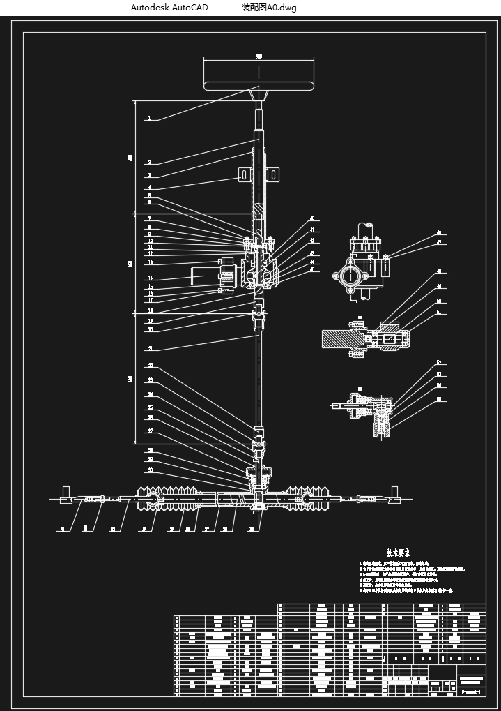
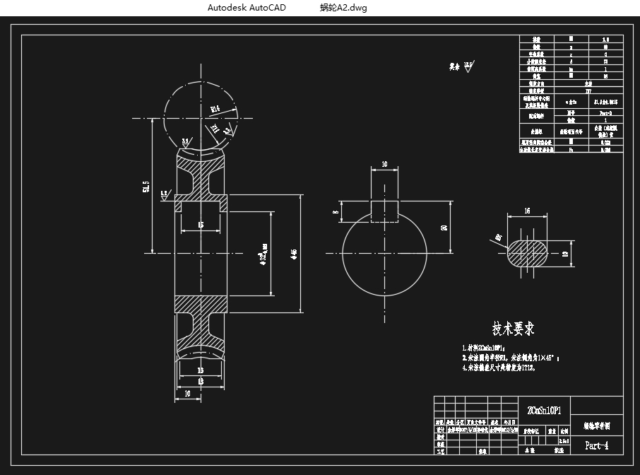
本文主要介绍了电动助力转向系统相关分总成的结构、形式,并为爱丽舍7164型轿车选择合适的EPS以替代其原本的液压助力转向系统,重点对蜗轮蜗杆减速机构以及齿轮齿条式转向器进行了设计、选型、计算,并进行了校核。
关键字:转向;爱丽舍7164型轿车;电动助力转向;蜗轮蜗杆减速;齿轮齿条式转向器
ABSTRACT
Elysee 7164 sedan is a compact car produced by Dongfeng Peugeot Citroen Automobile Company, and its steering system is a Hydraulic Power Steering System (HPS). In recent years, due to the constantly mature technology and the continuous development of the Electric Power Steering System (EPS), there are many modern autos equipped with EPS. Compared with Hydraulic Power Steering System, EPS abandons hydraulic cylinders, hydraulic valves etc., using a motor and a speed reduction mechanism for steering assistant, whose structure is simple and compact, and therefore the research of the system has become one of the most popular tasks among the major companies. EPS prospects immeasurable. [资料来源:Doc163.com]
This paper mainly introduces the structure and form of the relevant sub-assembly of the electric power steering system, and selects the appropriate EPS for the Elysee 7164 sedan to replace its original hydraulic power steering system. In addition, this paper focuses on how the worm gear reducer and rack-and-pinion steering gear were designed, selected, calculated, and checked.
Keywords:Steering; Elysee 7164 sedan; EPS; worm reducer; rack-and-pinion steering gear
爱丽舍DC7164轿车部分参数
轴距L/mm 2540
总长/mm 4305
总宽/mm 1707
总高H(空载)/mm 1413
前悬/mm 866
后悬/mm 899
前轮距/mm 1423
后轮距/mm 1424
最小转弯半径R(按前外轮)/mm 5250
最小离地间隙/mm 130±5
接近角 17°
离去角 18°
整车整备质量m0/kg 1125
前轴轴载质量mf1/kg 700
后轴轴载质量mr1/kg 425
满载总质量ma/kg 1500
前轴轴载质量mf2/kg 817
后轴轴载质量mr2/kg 683
轮胎规格 185/60 R14
[资料来源:www.doc163.com]
[资料来源:http://Doc163.com]

[来源:http://www.doc163.com]
目录
摘要 I
ABSTRACT II
第1章 绪论 1
1.1 汽车转向系统的简单介绍 1
1.2 电动助力转向系统的研究现状 2
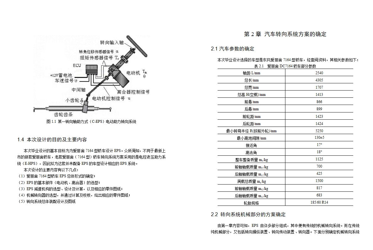
1.3 电动助力转向系统的工作原理 2
1.4 本次设计的目的及主要内容 3
第2章 汽车转向系统方案的确定 4
2.1汽车参数的确定 4
2.2 转向系统机械部分的方案确定 4
2.2.1 转向操纵机构 5
2.2.2 转向传动机构 5
2.2.3 机械转向器结构形式的确定 5
2.2.4 齿轮齿条式转向器方案确定 6
2.3 电动助力转向系统方案的确定 7
2.3.1 减速机构结构形式 7
2.3.2减速机构布置位置 8
第3章 电动助力转向系统主要部件的确定 10
3.1 电动机的选择 10
3.1.1 部分计算扭矩的确定 10
3.1.2电动机参数的确定 14
3.2 电磁离合器的选择 14
3.3 扭矩传感器的选择 15
第4章 EPS减速机构的设计 16
4.1 蜗轮蜗杆材料的选择 16
4.2 蜗轮蜗杆传动的设计计算 16
4.2.1设计要求 16
4.2.2选择蜗杆传动类型 16
4.2.3蜗杆模数及分度圆直径的确定 17
4.2.4蜗杆与蜗轮的主要参数及几何尺寸的确定 18
4.2.5 蜗轮齿面弯曲疲劳强度的校核 19
4.3 蜗杆轴的设计及校核 21
4.3.1蜗杆轴的设计 21
4.3.2 蜗杆轴的校核 22
4.3.3 蜗杆轴轴承的选取与校核 25
第5章 机械转向器的设计 28
5.1 齿轮齿条式转向器的概述 28
5.1.1转向器的设计要求 28
5.1.2转向器的计算载荷确定 28
5.2 转向器中齿轮轴的设计计算 29 [来源:http://www.doc163.com]
5.2.1 齿轮轴材料的选择 29
5.2.2 齿轮轴许用应力的计算 29
5.2.3齿轮模数的确定 30
5.2.4齿轮参数的确定 32
5.2.5齿轮强度的校核 32
5.2.6 齿轮轴的设计 35
5.2.7 齿轮轴的校核 36
5.2.8 齿轮轴轴承的设计及校核 40
5.3 齿条的设计 42
5.3.1 齿条的概述 42
5.3.2 齿轮齿条传动方案的选择 42
5.3.3 齿条的材料及参数的计算 43
5.4 间隙调整弹簧的设计 44
5.4.1 间隙调整机构概述 44
5.4.2 弹簧的设计要求 44
5.4.3 弹簧的选材及参数确定 44
第6章 结论 47
参考文献 48
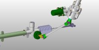
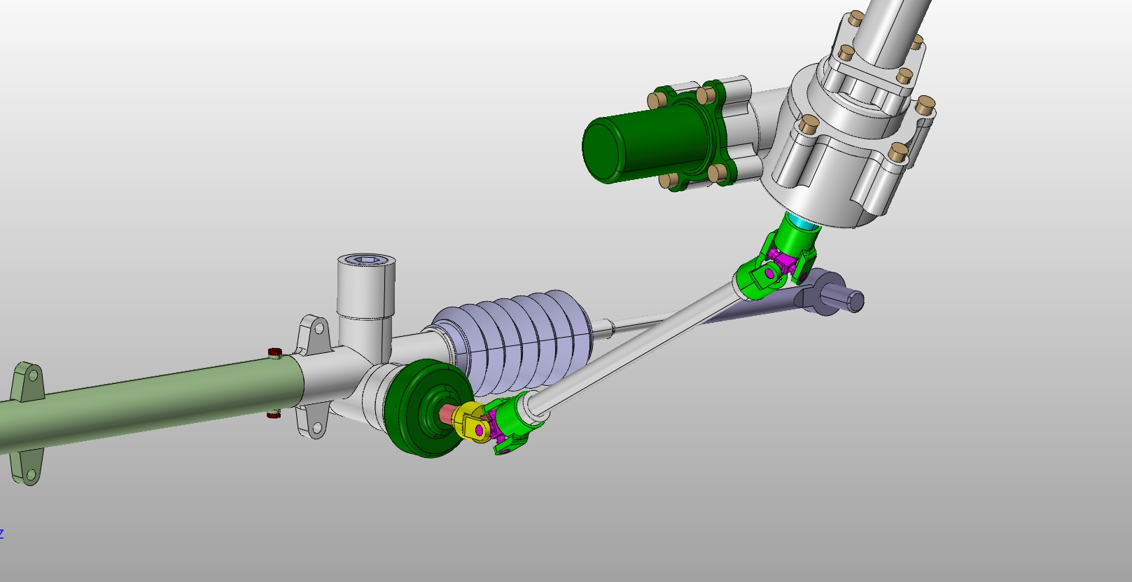
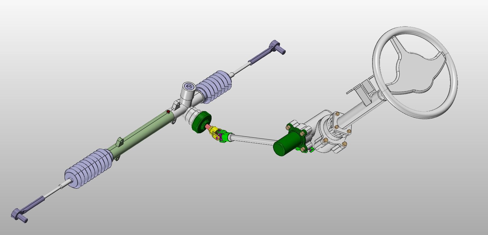
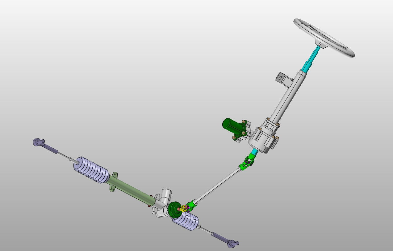
附录A CATIA三维图预览 49
A-1 三维零件图预览 49
A-2 三维装配图预览 54 [资料来源:http://www.doc163.com]
附录B 部分基于matlab的强度校核 59
致谢 60 [资料来源:http://www.doc163.com]
上一篇:依维柯轻型客车扭簧与前减振器总成三维设计(含STP三维图)