
纯电独立驱动房车底盘结构设计(含CAD图,CATIA三维图)(英文版)
纯电独立驱动房车底盘结构设计(含CAD图,CATIA三维图)(英文版)(任务书,开题报告,文献摘要,外文翻译,论文说明书8000字,CAD图纸4张,CATIA三维图)
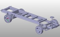
Structural design of pure electric independent drive recreational vehicle chassis
Abstract
The chassis is the main structure of the pure electric independentdrive recreational vehicle.Most parts of the electric vehiclehave to rely on the chassis to be fixed and connected.The main part of it is bear the overall vehicle load, also is the key component of the entire electric recreational vehicle. Therefore, the chassis structure should have the enough yield strength and the ultimatelimit stiffness.It should be complete with enough properties in response to external pressure generated when the corresponding dynamic characteristics, in order to reduce the vibration intensity of the vehicle. The main structure of performance directly determines the lateral stability performance of pure electric vehicles on the road surface, the steering wheel steering safety performance, and the internal passenger of the cab or thecarriage ride comfort permanenceon the uneven road conditions above.
The chassis system of the pure electric recreationalvehicle and the traditional recreationalvehicle is different from the other parts in addition to the engine, transmission and transmission system, the other parts of the chassis are approximately about the same. The main purpose of the chassis is to support all parts of the vehicle, such as the vehicle head, vehicle frame and vehiclecarriage, and other components of the fixedvehicle, soas to form a whole integrated structure. At the same time,the electric energy in the powerbattery is transmitted to the motor controller, and the wheel is directly driven by the wheel hub motor to drive thevehicle forward.
First of all, this thesis adopt the parameter requirements of this subject and the prerequisite for reference of similar models under the calculating parameters of electric recreationalvehicle chassis design independently, while the completion of the dimension type system requirements is related to the chassis structure. Then I have finished the 3D solid modeling and the assembly of various parts of the overall structure of the chassis with CATIA software, and then view of the effect on the overall structure of the appearance of a recreationalvehicle chassis was modified, while the completion of the three-dimensional modeling into two-dimensional drawings of the operations, in order to determine the overall structure of pure electric vehicle chassis and the corresponding to the design drawings.By the end of the basic parameters on the vehicle chassis 3D models and 2D drawings of the control and research, it can be found and modifiedin the structure design flaw, and perfect chassis overall structure design plan, to ensure that the actual production can be successfully completed. [资料来源:https://www.doc163.com]
Keywords: pure electric vehicle chassis design;3D modeling; parameter design
[资料来源:http://Doc163.com]


[资料来源:Doc163.com]


Contents
Chapter 1 Introduction 1
1.1Introduce the basic structure of chassis 1
1.2Chassis design principle 1
1.3Three types of chassis selection 2
[资料来源:http://doc163.com]
Chapter 2 Determine the main parameters of chassis 6
2.1Determination of dimensional parameters 6
2.1.1 Overall dimension 6
2.1.2 Wheelbase 6
2.1.3 Front and rear track 7
2.1.4 Front and rear suspension 7
2.1.5 Ground clearance 8
2.1.6 Minimum turning radius 8
2.2 Determine the quality parameters 8
2.2.1 Complete vehicle kerb mass 8
2.2.2 Loading quality 9
2.2.3 Quality coefficient..........................................................................................................9
2.2.4 Axle load distribution......................................................................................................9
Chapter 3 The main structure and selection of recreational vehicle..............................................11
3.1Motor selection 11
3.1.1According to maximum speed 12
3.1.2 According to acceleration time.....................................................................................12
3.1.3 According to maximum climbing grade.......................................................................13
3.1.4 According to the performance of motor........................................................................13
3.2Motor controller selection 14
3.3Power battery selection 15
3.4Drive form selection 16
3.5Suspension system selection 16
3.6Tire selection 17
3.7Brake system selection 17
3.8 Steering system selection.....................................................................................................18 [资料来源:Doc163.com]
Chapter 4Overall calculation and analysis of recreational vehicle 19
4.1The calculation of dynamic performance 19
4.1.1Maximum speed 19
4.1.2 Acceleration time 20
4.1.3Maximum climbing grade 20
4.2The calculation of braking performance 21
4.2.1 Braking performance 21
4.2.2Brake deceleration calculation 21
4.2.3Braking torque calculation 22
4.3The calculation of steering performance 22
4.3.1 Steering gear selection 22
4.3.2Maximum rotation angle 22
4.3.3Maximum internal wheel angle 22
4.3.4 Minimum turning radius 23
Chapter 5CATIA modeling 24
5.1Chassis cab modeling 24
5.2Suspension modeling 24 [资料来源:https://www.doc163.com]
5.3Motor modeling 25
Chapter 6Finite element analysis of frame 26
6.1 Frame modeling.....................................................................................................................26
6.2 Geometric models..................................................................................................................26
6.3 Meshpartition........................................................................................................................26
6.4 Frame load analysis...............................................................................................................27
6.4.1Static load.....................................................................................................................27
6.4.2 Dynamic load................................................................................................................27
[版权所有:http://DOC163.com]
6.5 Fully loaded bending condition of analysis.........................................................................28
Chapter7 Conclusion and prospect 30
7.1 Conclusion 30
7.2 Prospect 30
References......................................................................................................................................32 [来源:http://Doc163.com]
上一篇:本田crv机械式手动变速器设计(含CAD图,CATIA三维图)
下一篇:基于CFD的车用消声器流场分析(含CAD图,CATIA三维图)