
电动MPV四驱动力分配系统设计(含CAD零件装配图)
电动MPV四驱动力分配系统设计(含CAD零件装配图)(任务书,开题报告,论文说明书16700字,CAD图纸13张)
摘要
四轮驱动系统经过数十年的发展,已经被各汽车厂商广泛应用于乘用车领域。而随着科技的发展,各种传统理念的智能化,消费者已经不再满足于全时四驱形式的车辆,而更倾向于驾驶能够自主切换两驱、四驱模式的汽车,即智能四驱车辆。
智能四驱,顾名思义,即是车辆能自行根据当前路面及车辆运行情况,迅速有效调整车辆驱动模式,以求获得更好的车辆通过性和驾驶稳定性。
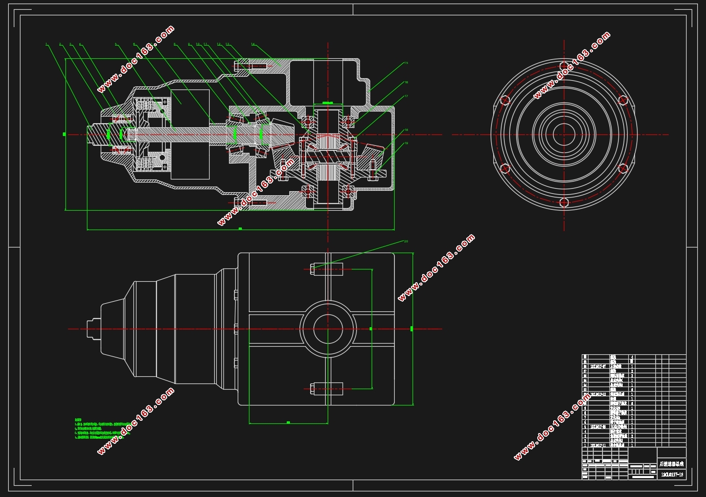
本次设计基于电动MPV车型,对比同类别车型使用的智能四驱系统,参考设计适合本车型驾驶条件、驾驶人群的智能四驱系统,着重分析了该智能四驱系统的工作原理,并对后桥减速器的主要参数进行了分析、设计、计算、校核。
关键词:智能四驱;动力分配;DPS;减速器
Abstract
After decades of development, AWD has been used widely in cars by most of the carmakers. With the technology progress, more and more traditional things gain its intelligent concepts. And the consumers are no longer satisfied in AWD cars. They are more interested in real-time AWDs, because it could switch from 2WD to 4WD automatically. [来源:http://www.doc163.com]
Just as its name implies, real-time AWD could adjust the driving mode rapidly and effectively according to the current road situation and car running state in order to gain much more bettermobility over unprepared terrain and driving stability.
This design basis on the electric MPV, analysis the working principles of the real-time AWD system emphatically, basis on the comparisons with similar cars in the same class, reference with the driving situations and the users’ experience who will drive the electric MPV. And finished the analysis, design, calculation and check to the key parameters of the rear axle reducer.
Key Words:Real-time 4WD; DPS; Rear axle reducer
[资料来源:http://www.doc163.com]


[版权所有:http://DOC163.com]
目录
第一章绪论 1
1.1 目的及意义 1
1.2 国内外现状 1
1.3 本文主要研究内容 2
第二章动力分配单元 3
2.1 动力分配单元概述 3
2.2 动力分配单元方案选择 3
第三章扭矩控制单元设计 5
3.1 扭矩控制单元概述 5
3.2 多片离合器基本参数选择与计算 5
3.2.1 摩擦材料的选择 5
3.2.2 心板材料的选择 5
3.2.3 摩擦片件数的选择 6
3.2.4 储备系数的选择 6
3.2.5 冷却油槽 6
3.2.6 摩擦片尺寸的选择 6
3.2.7 摩擦片尺寸校核 8
3.2.8 压板行程 8
3.3 膜片弹簧设计 8
3.3.1膜片弹簧的载荷与变形 8
3.3.2膜片弹簧的基本参数的选择 9
3.3.3 膜片弹簧工作点位置选择 11
[资料来源:Doc163.com]
3.3.4 强度校核 13
3.4 离合器内轮毂与外导套设计 14
3.4.1 渐开线花键设计 14
3.4.2 花键强度校核 15
3.5 液压控制系统原理分析 17
3.5.1 前进挡的起动与加速行驶 17
3.5.2 前进挡的定速巡航 18
3.5.3 前进档的减速行驶 18
3.5.4 倒车挡的起动与加速行驶 19
3.5.5 倒车挡的恒速行驶 20
3.5.6 倒车挡的减速行驶 20
3.5.7 热敏开关与减压阀 21
3.6 单向凸轮机构 22
第四章后减速器、差速器设计 23
4.1 后减速器概述 23
4.2 后减速器基本参数选择与计算 23
4.2.1 主减速比确定 23
4.2.2 后减速齿轮计算载荷确定 23
4.2.3 后减速器齿轮基本参数选择 24
4.2.4 后减速器齿轮的集合计算 25 [资料来源:Doc163.com]
4.3 后减速器强度校核 26
4.3.1 后减速器齿轮材料的选择 27
4.3.2 后减速器齿轮的强度计算 27
4.3.3 后减速器齿轮的弯曲强度计算 28
4.3.4 齿轮接触强度的计算 29
4.4 后差速器基本参数选择与计算 29
4.4.1 行星齿轮数选择 29
4.4.2 行星齿轮球面半径 的确定 29
4.4.3 计算转矩 30
4.4.4 行星齿轮与半轴齿轮齿数的选择 30
4.4.5 初步确定圆锥齿轮模数及半轴齿轮节圆直径 31
4.4.6 压力角的选取 31
4.4.7 行星齿轮安装孔的直径及其深度 31
4.4.8 差速器齿轮的集合计算 31
4.5 后差速器强度校核 33
4.5.1 差速器齿轮材料选择 33
4.5.2 差速器齿轮强度计算 33
第五章结论 34
参考文献 35
附录 37 [资料来源:http://Doc163.com]
致谢 41 [资料来源:http://doc163.com]
上一篇:轿房车后部空间拓展(折叠框架帐篷结构)设计(含CAD图,CATIA三维图)
下一篇:电动MPV驱动桥设计(含CAD零件装配图,CATIA三维图)