
MQ4040单臂架门座起重机回转机构设计(含CAD图,SolidWorks三维图)
MQ4040单臂架门座起重机回转机构设计(含CAD图,SolidWorks三维图)(任务书,开题报告,外文翻译,论文说明书13000字,CAD图纸4张,SolidWorks三维图)
摘要
近几年来,随着物流行业的迅猛发展,港口产业也日益壮大。门座式起重机作为一种高效率的起重运输机械在港口被广泛使用。回转机构是门座起重机的主要工作机构之一。回转机构对于起重机的整体性能有决定性的影响。因此,对门座起重机回转机构的研发设计做进一步探讨有非常重要的现实意义。
本文设计以MQ4040单臂架门座起重机为研究对象,使用SolidWorks及Adams软件对其进行总体设计以及回转机构设计。主要工作如下:
(1)在MQ4040门座起重机的总体设计中,首先对起重机进行了大体设计。随后对货物水平位移补偿系统和臂架自重平衡系统进行设计及校核。最后,对起重机设计的相关载荷进行计算,并对轮压、抗倾覆稳定性校核和抗风防滑安全性进行验算。
(2)在回转机构设计中,首先对回转机构布置进行选择,随后进行回转支承装置及回转驱动的设计计算。最后使用Atuocad软件进行相关工程图纸的绘制。
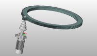
(3)在三维建模中,使用SolidWorks软件对回转机构各个零件进行三维建模。然后将所有零件模型进行装配,组成回转机构。经过分析,模型无干涉,可进行下一步的Adams运动学仿真。
[来源:http://www.doc163.com]
(4)在Adams运动学仿真中,将所建的三维模型导入Adams软件,通过对零件添加合适的约束和驱动,完成动力学仿真。最后输出仿真结果,经分析,仿真结果符合设计要求。
关键词:门座起重机;回转机构;总体设计;建模仿真
Abstract
In recent years, with the rapid development of the logistics industry, the port industry has also grown. Portal cranes are widely used in ports as a highly efficient lifting and transporting machine. The slewing mechanism is one of the main working mechanisms of the portal crane. Slewing mechanism has a decisive influence on the overall performance of the crane. Therefore, it is of great practical significance to further explore the design of the portal crane slewing mechanism.
This article designed the MQ4040 single-arm portal crane as the research object, using SolidWorks and Adams software for its overall design and rotary mechanism design. The main work is as follows:
(1) In the overall design of the MQ4040 portal crane, the general design of the crane was first performed. Subsequently, the horizontal displacement compensation system and the boom self-balancing system were designed and checked. Finally, the relevant load of the crane design is calculated, and the wheel pressure, anti-overturning stability check, and anti-skid safety are checked. [来源:http://www.doc163.com]
(2) In the design of the slewing mechanism, the slewing mechanism arrangement is first selected, and then the slewing bearing device and the slewing drive are calculated and calculated. Finally use Atuocad software to draw related engineering drawings.
(3) In the three-dimensional modeling, SolidWorks software is used to perform three-dimensional modeling of various parts of the slewing mechanism. Then all the part models are assembled to form a slewing mechanism. After analysis, the model has no interference and can perform the next Adams kinematics simulation.
(4) In the Adams kinematics simulation, the built 3D model was imported into Adams software, and dynamic simulation was completed by adding appropriate constraints and drivers to the parts. Finally, the simulation results are output. After analysis, the simulation results meet the design requirements.
Keywords: Portal crane; Slewing mechanism; Overall design; Modeling and Simulation
设计参数表
项目名称 性能参数
[版权所有:http://DOC163.com]
起重量 40t(吊钩)
25t(抓斗)
工作幅度 最大幅度:40m
最小幅度:13m
起升高度 轨上:30m(吊钩)20m(抓斗)
轨下:15m
机构工作速度 起升机构:30m/min(吊钩)40m/min(抓斗)
变幅机构:30m/min
回转机构:1r/min
运行机构:26m/min
机构工作级别 整机:A8
起升机构:M7
变幅机构:M7
回转机构:M7
运行机构:M5
轨距/基距 10.5m/12m
计算风压 qⅠ=15m/s
qⅡ=20m/s
qⅢ=33m/s(突发阵风)55m/s
货物的偏摆角 臂架摆动平面:αⅠ=3°;αⅡ=10°
垂直于臂架摆动平面:αⅠ=3°;αⅡ=12° [来源:http://www.doc163.com]
冲击运行速度 25m/min
工作状态最大阵风作用 qⅢ=765N/m2
非工作状态最大风作用 qⅢ=1890N/m2


[资料来源:www.doc163.com]


 [版权所有:http://DOC163.com]

目录
第1章绪论 1
1.1 课题的研究目的和意义 1
1.2 国内外的研究现状分析 1
1.3 课题的研究内容 3
1.4 设计技术方案 3
第2章 MQ404门座起重机总体设计 4
2.1 设计参数 4
2.2 水平位移补偿系统及臂架自重平衡系统校核 5
2.2.1 水平位移补偿系统校核 5
2.2.2 臂架自重平衡系统校核 6 [来源:http://www.doc163.com]
2.3 载荷的计算 7
2.3.1 自重载荷 7
2.3.2风载荷 9
2.3.3碰撞载荷 11
2.4 轮压的计算 12
2.5 整机抗倾覆稳定性计算 14
2.5.1 无风静载工况 14
2.5.2 有风动载工况 14
2.5.3 突然卸载或吊具脱落工况 15
2.5.4 非工作状态暴风侵袭工况 15
2.6 抗风防滑安全性 16
2.6.1 正常工作状态抗风防滑安全性计算 16
2.6.2 非工作状态抗风防滑安全性计算 16
第3章起重机回转机构设计 18
3.1 回转机构简介 18
3.2 回转支承装置设计 18
3.2.1 回转支承装置简介 18
3.2.2 回转支承计算载荷 19
3.2.3 回转支承选型 21
3.3 回转驱动装置设计 21
3.3.1 回转驱动装置简介 21
[资料来源:http://Doc163.com]
3.3.2 回转驱动装置计算载荷 21
3.3.3 电机的选型及校核 22
3.3.4 减速器选型 23
3.3.5 极限力矩联轴器选型 24
3.3.6 制动器选型 24
第4章回转机构建模与仿真 25
4.1 回转机构SolidWorks三维建模 25
4.2 回转机构的ADAMS运动学仿真 28
第5章环境影响及经济性分析 31
5.1 环境影响分析 31
5.2 经济性分析 31
第6章总结与展望 32
6.1 全文总结 32
6.2 不足与展望 32
参考文献 33
致谢 34 [资料来源:www.doc163.com]
下一篇:40万吨/年硫酸转化工段热管省煤器的设计(含CAD零件图装配图)