绳轮式玻璃升降器设计(含CAD零件图装配图,CATIA三维图)

绳轮式玻璃升降器设计(含CAD零件图装配图,CATIA三维图)(任务书,开题报告,文献摘要,外文翻译,论文说明书12000字,CAD图5张,CATIA三维图)
摘要
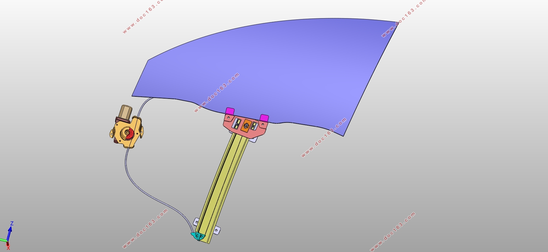
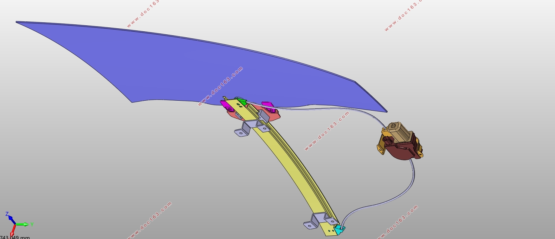
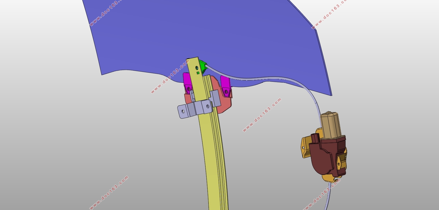
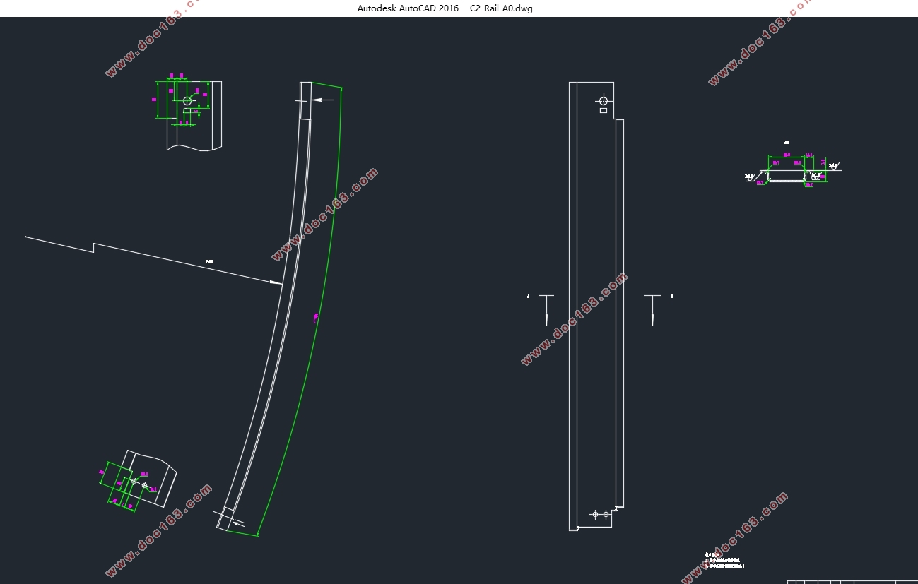
本文介绍了车窗玻璃升降器的主要分类和结构,并对绳轮式。玻璃升降器的整个设计过程做了一个简要的概述,同时结合给定的车门参数进行了绳轮式升降器主要零件的结构设计。在完成升降器结构设计的同时,本文还对升降器滑块和导轨的受力情况提出了力学分析模型,并利用有限元分析软件对升降器在上止点和下止点这两个极限位置的受力情况进行了仿真分析,验证了设计方案的可行性。最终得到一个符合实际使用要求的绳轮。式玻璃。升降器设计方案。本文从最原始的设计参数开始,一步步展现设计方案的形成过程,总结了绳。轮式玻。璃升降器的开发流程和设计思路,对于进行新车型开发的整车厂具有一定的参考价值。
关键词:绳轮式玻璃升降器;力学模型;有限元分析
Abstract
This paper introduces the main classification and structure of the window lifter. The whole design process of the rope-wheeled window lifter has been briefly described, and the structural design of the main parts of the riser has been carried out in conjunction with the given door parameters. At the same time, the mechanics analysis model of the lifter slider and the rail force is put forward, and the finite element analysis software is used to analyze the two limit positions of the hoist in the top dead center and the bottom dead center The feasibility of the design scheme is verified by simulation analysis. And finally get a realistic use of the requirements of the rope- wheeledglass regulator design. This paper begins with the most original design parameters, and shows the development process of the design scheme step by step. It summarizes the development process and design idea of the rope-wheeled window regulator, which has certain reference value for the new vehicle factory. [来源:http://Doc163.com]
Key Words:the rope-wheeled window regulator; Mechanics model; Finite element analysis
[资料来源:http://doc163.com]

 [版权所有:http://DOC163.com]
目录
第1章绪论 1
1.1引言 1
1.2玻璃升降器的发展现状 1
1.3研究的目的和意义 1
第2章玻璃升降器的分类与介绍 3
2.1臂式玻璃升降器 3 [资料来源:www.doc163.com]
2.2柔性玻璃升降器 3
2.3丝杆玻璃升降器 4
第3章绳轮式玻璃升降器的设计 5
3.1玻璃形状参数的确定 5
3.1.1窗框的尺寸参数 5
3.1.2车窗玻璃的曲率 5
3.2导轨参数的确定 6
3.2.1确定导轨空间曲率 6
3.2.2确定导轨安装位置 7
3.2.3确定导轨长度和横截面 10
3.3其他附件设计 12
3.3.1滑块设计 12
3.3.2滑轮及滑轮架设计 13
3.3.3滑绳架设计 14
3.3.4电机座板设计 15
第4章导轨受力分析 16
4.1滑块受力分析 16
4.2导轨受力分析 19
第5章玻璃升降器有限元分析 21
5.1导轨有限元模型的建立 21
5.2导轨有限元分析过程 22
5.3导轨有限元分析结果 23 [资料来源:http://www.doc163.com]
第6章总结和展望 26
6.1设计总结 26
6.2展望 26
参考文献 27
附录 28
附录A 28
致谢 29
[来源:http://www.doc163.com]
上一篇:综合集装箱吊具伸缩梁结构设计(含CAD零件图装配图)
下一篇:轿车座椅疲劳试验台加载系统设计(含CAD零件图装配图)
