
动车轮对组装机液压系统设计(含CAXA图)

动车轮对组装机液压系统设计(含CAXA图)(任务书,开题报告,外文翻译,论文说明书15000字,CAXA图纸4张)
摘要
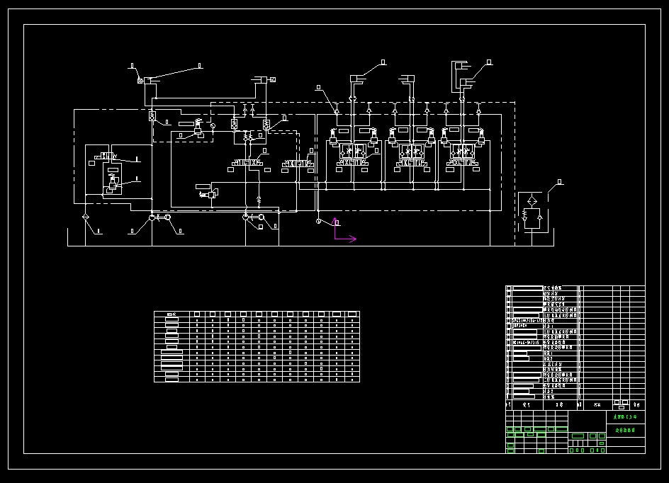
动车轮对组装机液压系统主要给左右油缸、活动梁滑块体移动油缸、活动梁定位油缸等提供动力。油箱、电动机、液压阀、液压泵、阀块体、压力传感器、压力计、滤清器、油管通道等构成了液压系统,所有的液压阀和压力计等均安装在阀块体上,而所有集成块都装在油箱上。轮对压组机的液压系统由主要液压系统和次要液压系统构成。主要液压系统采用伺服电机带动齿轮泵工作的方式,完成轮对组装机设备上的左右油缸快进、工进和快退及左右插板定位油缸和定位销锁紧油缸的快进、工进和快退等动作,次要液压系统采用电动机带动齿轮泵工作的方式,控制主要液压系统中液控单向阀的通闭和完成左右油缸的快退的动作。
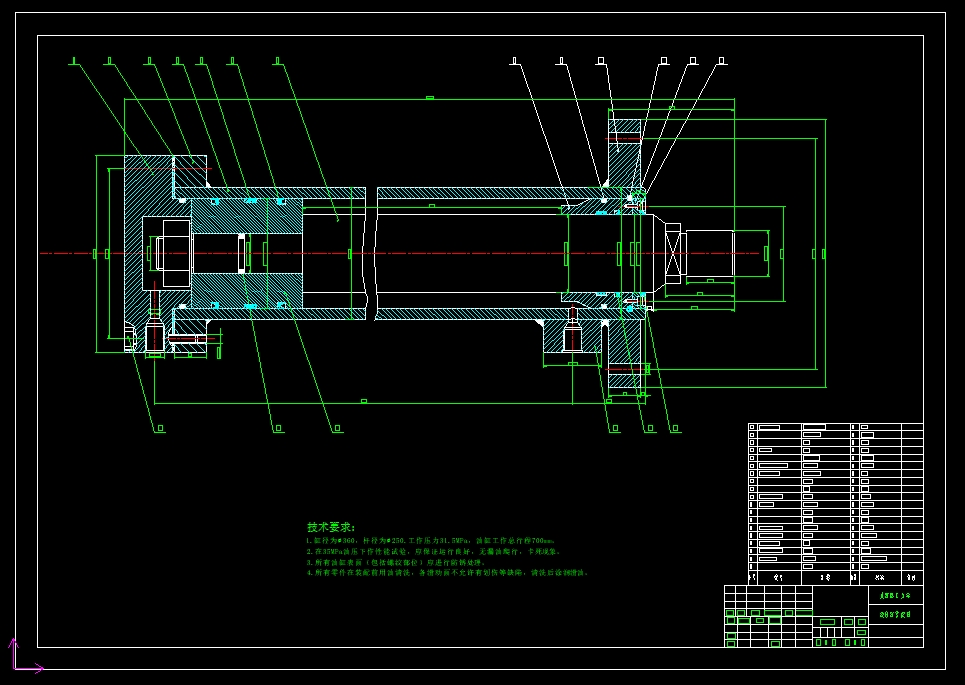
本文主要进行了液压系统的设计、液压缸的设计和阀块体的设计。液压系统的设计内容包含液压元件的选型及绘制液压原理图。液压执行元件的设计内容包括左右油缸的设计,并绘制油缸装配图和活塞零件图。集成块设计内容包括孔道布局设计以及绘制三维图和工程图。
关键词:轮对组装机、液压系统、液压执行元件、集成块
ABSTRACT
The hydraulic system of the moving wheel is mainly powered by the left and right cylinders, the movable beam slider moving cylinder, the movable beam positioning cylinder and so on. Oil pressure, oil pressure, oil pressure, water pressure, water pressure, water pressure, oil pressure, water pressure, water pressure, And all manifolds are mounted on the tank. The hydraulic system of the wheel press is composed of the main hydraulic system and the secondary hydraulic system. The main hydraulic system uses the servo motor to drive the gear pump work way, completes the wheel on the assembly machine equipment on the right and left the cylinder fast forward, the work into and rewind and left and right board positioning cylinder and positioning pin lock cylinder fast forward, Fast reverse the action, the secondary hydraulic system using the motor to drive the gear pump work, control the main hydraulic system in the hydraulic control valve closed and complete the left and right cylinder rewind the action. [版权所有:http://DOC163.com]
This paper mainly designed the hydraulic system, the design of the hydraulic cylinder and the design of the valve block. The design of the hydraulic system includes the selection of hydraulic components and drawing the hydraulic schematic. The design of the hydraulic actuator includes the design of the left and right cylinders and the drawing of the cylinder assembly and the piston parts. The manifold design includes the hole layout design and the drawing of the 3D drawings and drawings.
Key Words:Wheel assembly machines, hydraulic systems, hydraulic actuators, manifolds
本文研究的主要内容
本文主要研究动车轮对组装机的液压系统设计[3],设计自动化程度高,工作可靠的液压系统,使轮对组装机完成更多尺寸不同、样式各异的轮对的组装工作,形成具有中国特色的工业级动车轮对组装机产品系列。
技术数据
压头油缸最大工作力 ≥3000KN [来源:http://www.doc163.com]
压头油缸数量 2
压头油缸柱塞最大行程 700mm
中间梁最大开口 1350mm
上梁至底座垂向距离 2150mm
活动梁定位可调距离 13×200
压头油缸活塞杆进给速度 0~25(可调)
[版权所有:http://DOC163.com]
压头油缸活塞杆压装速度 0~25(可调)
两顶尖最大承重 10000kg
两顶尖最大预紧力 100kN
电动小车最大托起重量 5000kg
电动小车回转角度 180°
检测系统精度 ≤0.03mm [资料来源:www.doc163.com]
液压系统工作压力 31.5MPa
系统电压 3×380V
系统频率 50Hz
辅助电压 DC24V
总装机容量 50kW
压力传感器精度 ≤0.15%
测量精度 <0.2
邮箱容积 1000L
最大压装/拆卸车轮直径 φ1255mm
最小压装/拆卸车轮直径 φ700mm [资料来源:Doc163.com]
轮对最大重量 3500kg
双主油缸间通过轴最大长度 3000mm
[资料来源:http://doc163.com]


[来源:http://Doc163.com]

目 录
第1章 绪论 1
1.1引言 1
1.2现状分析 1
1.2.1国内现状 1
1.2.2国外现状 1
1.3本文研究的主要内容 2
第2章 动车轮对组装机的总体设计 3
2.1技术数据 3
2.2机械系统 3
2.3测量系统 5
2.3.1测量位置 5
2.3.2标定及校正装置 5
2.3.3测量系统的结构 5
2.4液压系统 6
第3章 动车轮对组装机的液压系统设计 8
3.1 液压系统的设计要求及其设计参数 8
3.1.1对液压系统的要求 8
3.1.2液压系统设计参数 9
3.2各液压缸的载荷力计算 9
3.2.1左右主油缸的载荷力 9
3.2.2插板定位油缸的载荷力 9
3.2.3活动梁插销锁紧油缸的载荷力 9
3.3液压系统主要参数计算 10
3.3.1初选系统工作压力 10
3.3.2计算液压缸的主要结构尺寸 10
3.3.3计算液压缸实际工作压力 11
3.3.4计算油缸实际所需要的流量 12
3.4 液压系统和液压控制系统的设计 12
3.4.1制定液压系统方案 12
3.4.2设计液压控制系统 14
3.5液压元件的选择 15
3.5.1液压泵的选择 15
3.5.2电动机功率的确定 17
3.5.3液压阀的选择 18
3.5.4油管内径计算 18
3.6液压系统性能验算 19
3.6.1验算回路中的压力损失 19
[资料来源:https://www.doc163.com]
3.6.2液压系统发热温升计算 21
第4章 液压执行元件的设计 24
4.1缸筒 24
4.1.1缸筒与缸盖的连接 24
4.1.2对缸筒的要求 24
4.1.3缸筒计算 24
4.1.4缸筒底部厚度 25
4.1.5缸筒与前缸盖的连接强度校核 25
4.2活塞组件设计 26
4.2.1活塞设计 26
4.2.2活塞与活塞杆的连接结构 27
4.2.3活塞杆设计 28
4.2.4活塞杆及连接件强度校核 29
4.2.5活塞杆液压缸稳定性校核 30
4.3液压缸油口设计 31
第5章 液压集成块结构的设计 33
5.1液压集成块设计的一般原则 33
5.1.1设计依据 33
5.1.2集成块设计的一般规定 33
5.2集成块的设计 34
5.2.1集成块的设计内容 34
5.2.2集成块孔道立体示意图 34
5.2.3集成块零件工作图 35
5.2.4 集成块六视图 36
总 结 40
参考文献 41
附录A 42
附录B 43
附录C 44
附录D 45
致 谢 46 [来源:http://Doc163.com]
上一篇:10升流化床制粒机设计(含CAXA图,SolidWorks三维图)
下一篇:GXC800数控滚铣车复合机床设计-滚削部分(含CAD图)