
车桥总成制动力矩快速在线检测设备总体设计(含CAD图)
车桥总成制动力矩快速在线检测设备总体设计(含CAD图)(任务书,开题报告,外文翻译,论文说明书12000字,CAD图13张)
摘要
随着国家对汽车安全性能的日益重视,各项针对汽车结构及整车性能的检测设备层出不穷。由于车桥制动器制动力矩的大小及左右制动器制动力矩的差异对于整车行驶的安全性有着严重影响,因此能够检测制动器相应性能的试验台就显得十分重要。目前国内常用的惯性试验台有平板式与滚筒式。根据厂家的具体要求,本次将在滚筒式惯性试验台基础上设计转毂式电动模拟惯量制动力矩检测试验台。这种试验台采用电惯量模拟机械惯量的方式,不仅省去反复更换惯量盘的时间,也免去惯量盘与电惯量互相干涉的情况。试验台可以适应多种规格车桥的制动力矩检测需求,能够实现所需夹具、模拟惯量的快速适应,同时可满足在线生产检测的节拍需求并且可以对试验台进行信息化管理。
关键词:制动力矩、试验台、操作系统、总体设计
Abstract
With the growing importance of automobile safety performance, the emerging structure for the automobile and vehicle performance testing equipment emerge in endlessly. The difference between the braking torque of the axle brake and the braking torque of the left and right brakes has a serious impact on the safety of the vehicle, so it is very important to be able to detect the test bench of the corresponding performance of the brake. At present, the inertial test rigs commonly used in China are flat and drum type. According to the specific requirements of this time, this will be in the drum inertial test bed based on the design of hub-type electric analog inertia brake torque test bench. This kind of test bed adopts the method of simulating the mechanical inertia by the electric inertia, which not only eliminates the time of replacing the inertia disk repeatedly, but also eliminates the situation that the inertia disk and the electrical inertia interfere with each other. The test bed can meet the requirements of braking torque detection of various specifications of the axle, which can realize the fast adaptation of the required fixture and the simulation inertia, and can meet the beat demand of the online production test and can manage the test bed. [资料来源:http://www.doc163.com]
Keywords:Brake torque, test - bed, operating system, overall design
[资料来源:www.doc163.com]


目录
第1章 绪论 1
1.1课题提出的背景 1
1.2国内外的研究现状分析 1
1.3设计的基本内容与预期目标 2
1.3.1设计的基本内容 2
1.3.2设计的预期目标 2
1.4制动器性能要求 2
1.5本章小结 3
第2章 设计的总体技术方案 4
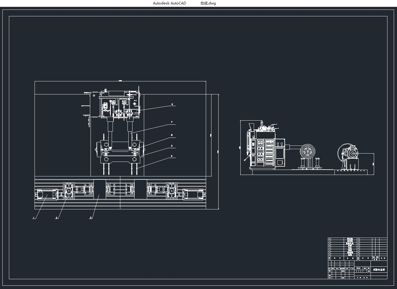
2.1试验台设计原理 4
2.2试验台基本结构设计 4
2.3方案的比较与选择 4
2.3.1试验台形式选择 4
2.3.2试验台总体技术方案 5
2.4试验过程节拍控制 7
2.5本章小结 8
第3章 驱动系统设计 9
3.1驱动系统参数计算 9
3.1.1汽车制动过程的简化模型 9
3.1.2电惯量模拟 10
3.2驱动系统结构 12
3.2.1驱动系统构成 12 [版权所有:http://DOC163.com]
3.2.2驱动系统的传感器 13
3.3本章小结 13
第4章 夹紧部分设计 15
4.1夹紧部分整体结构 15
4.2液压加载机构参数 15
4.3夹具的夹紧力计算 16
4.3.1车桥夹具夹紧力计算 16
4.3.2支撑座锁止机构夹紧力计算 17
4.4本章小结 18
第5章 操作系统设计 19
5.1操作台设计 19
5.1.1操作柜 19
5.1.2操作柜显示界面 20
5.2电气控制系统 21
5.3本章小结 22
第6章 设备的现场布置 23
6.1厂内布置地选择 23
6.2场地平面布置 23
6.2.1总体布置 23
6.2.2管线路布置 24
6.3安全防护 25
6.4本章小结 25
第7章 总结与展望 26
参考文献 27
附 录 28
致 谢 29
上一篇:燃料电池公交客车悬架设计(含CAD图,SolidWorks三维图)
下一篇:汽车轴承轧制过程形状视觉测量系统设计(含CAD图,CATIA三维图)