注射器盖注塑模具的设计(含CAD零件图装配图,UG三维图)
注射器盖注塑模具的设计(含CAD零件图装配图,UG三维图)(任务书,论文说明书10000字,CAD图10张,UG三维图)
摘 要
本次设计是对注射器盖进行注塑模具的工艺设计。本设计中所使用注塑模具的通用加工和设计步骤对注射器盖的加工流程进行全面的分析和正整理,确定其注塑加工的各项参数和注意事项。首先对该注射器盖相关i加工参数和工艺要求,对加工材料进行确定,选定好注射器盖的加工材料后,对该模具的工艺参数进行分析,在此基础上确定注塑机选用的型号为HTF80XB,以及对该型号的注塑机的可行性进行校核。然后对零部件的进行布局分析,本次设计中采用的是一模一腔的布局形式。对模具分型面的确定,确定了成型零部件的尺寸大小,以及对推出机构以及流道进行设计,最总完成模具的设计,确定该模具的装配流程和注意事项及相关维护需求。本次设计中结合大学学习到的相关知识,参考相关文献及书记,结合其他机械制图的知识完成了注射器盖的注塑模设计。同时采用Pro/e三维制图软件对注射器盖进行注塑模的设计,完成分模等相关工作。
关键词:注塑模;注射器盖;分型面;UG三维;
Abstract
This design is the process design of injection mold for the shaver shell in daily necessities. The general processing and design steps of the injection mold used in the design comprehensively analyze and straighten the processing flow of the shaver shell, and determine the parameters and precautions of the injection molding process. First of all, the related I processing parameters and process requirements of the shaver housing are determined. After the processing materials of the shaver housing are selected, the process parameters of the mold are analyzed. On this basis, the model selected for the injection molding machine is HTF 80 × B, and the feasibility of the injection molding machine is checked. Then the layout analysis the parts, the first mock exam is two cavity layout. To determine the parting surface of the mold, determine the size of the forming parts, design the pushing mechanism and flow channel, and complete the design of the mold, determine the assembly process, precautions and related maintenance requirements of the mold. In this design, the injection mold design of the shaver shell is completed by combining the relevant knowledge learned by the University, referring to the relevant literature and secretary, and combining with the knowledge of other mechanical drawings. At the same time, the 3D drawing software Pro / E is used to design the injection mold of the shaver shell and complete the mold division and other related work.
Keywords: injection mold; razor shell; parting surface; UG 3D;
尺寸要求
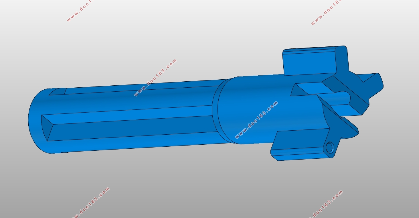
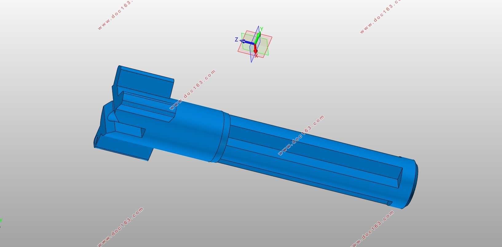
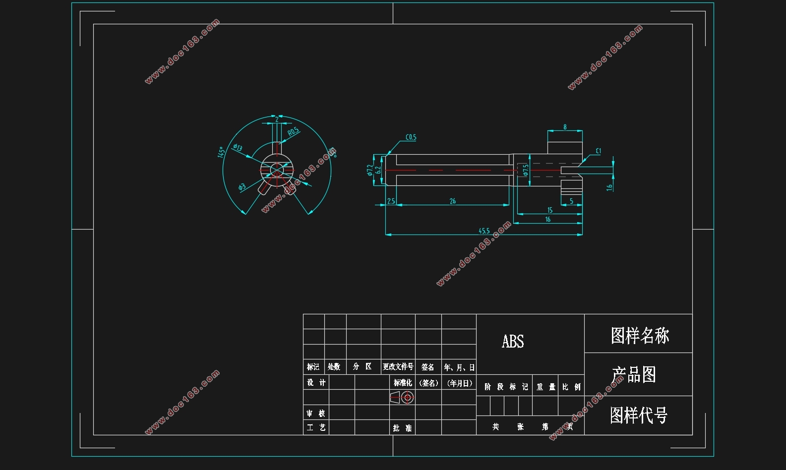
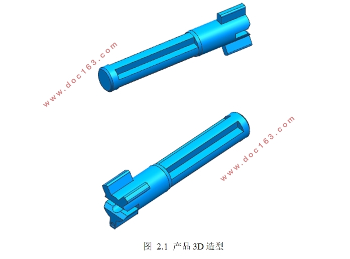
该注射器盖产品的立体形状详见图2.1所示,通过对该零部件的三维图纸分析,从中我们能够看出,该零部件在结构上是属于盖子的形状,其中间为空心状态,底面上存在固定螺丝的部位,此外该注射器盖在完成装配后不再需要打开,同时该零部件属于外壳,所以在表面要求比较光滑并无毛刺,此外,该零部件必须要和下配合固定在一起使用,所以内壁的尺寸要求较高。
[资料来源:Doc163.com]

 [资料来源:Doc163.com]
目录
摘 要 I
[资料来源:Doc163.com]
Abstract 1
第一章 绪论 5
第二章 注塑工艺分析 6
2.1 产量及生产要求 6
2.2 材料特性 6
2.3 零件图纸 6
2.3.1尺寸要求 6
2.3.2 精度确定 7
2.3.3 塑料制品形状 7
2.3.4 脱模斜度 7
2.3.5分型面选择 7
第三章 注塑机初选和型腔布局 9
3.1 注射机确定 9
3.2模具型腔数目计算 9
3.2.1 注射量的计算 9
3.2.2 制品体积 10
3.2.3 型腔数目 10
第四章 成型零件尺寸及结构 11
4.1 ABS收缩率(S) 11
4.2 型芯尺寸和结构设计 11
4.2.1 型芯长宽尺寸计算利用公式 11
4.2.2 型芯高度尺寸 12
4.3 型腔尺寸及结构设计 12 [资料来源:http://doc163.com]
4.3.1型腔长宽尺寸 12
4.3.2 型腔深度尺寸 12
4.3.3 型腔结构 13
第五章 模具结构 14
5.1模具结构图 14
5.2合模导向机构设计 14
第六章 浇注系统的设计 16
6.1 浇注系统概述 16
6.2 浇注系统设计 16
6.2.1 主流道设计 16
6.2.2 浇口的设计 17
6.2.3 排气糟设计 18
第七章 推出机构 19
7.1 概述 19
7.2 脱模及推出机构 19
7.2.1 脱模力 19
7.2.2 推出机构 19
第八章 冷却系统 21
8.1温度塑件品质影响 21
8.2 冷却系统设计规则 21
8.3 冷却时间计算 22
8.3.1模具材料 22
8.3.2冷却介质温度和流动状态 22
[来源:http://Doc163.com]
8.3.3模塑材料(塑料) 22
8.4 冷却参数计算 23
8.4.1 所需冷却水体积流量的计算 23
8.4.2冷却水在水孔内的传热速度 24
8.4.3冷却水孔与冷却水间的传热系数 24
8.4.4传热水孔总传热面积的计算 24
8.4.5冷却水孔总长度计算 25
8.5.6 冷却水道孔数计算 25
第九章 模具装配 27
9.1 模架选择 27
9.2模具成型机械关系校核 28
9.2.1 制品和流道体积 28
9.2.2注射机校核 28
结论 30
附图 31
参考文献 32
致 谢 33
[资料来源:http://www.doc163.com]
上一篇:塑料抽屉模具设计(含CAD零件图装配图,UG三维图)
下一篇:塑料收纳箱体注射模具设计(含CAD零件图装配图,UG三维图)
