汽车转向节的锻模(模具)设计(含CAD图,答辩记录)

汽车转向节的锻模(模具)设计(含CAD图,答辩记录)(任务书,开题报告,论文说明书17000字,CAD图6张,答辩记录)
摘要
本次毕业设计是完成汽车转向节的锻模设计。在确认好题目后,我先进行了资料的查阅,包括近年来国内的一些期刊论文以及国外的一些文献,对转向节的研究现状有了基础的了解。转向节是汽车生产上需要用到的高精度且形状较为复杂的零件,随着汽车行业的快速发展其需求量也相应增大。由于其形状非常特殊,按照传统的加工工艺不能满足其精度要求及强度要求,因此目前运用最广泛的的转向节加工技术即为锻造加工。在我查阅了专业的锻造技术书籍后,我开始对我所要研究的转向节进行分析,并最终确定了墩粗、预锻、终锻的工艺路线。在接下来对转向节锻模的设计过程中,我根据手中的零件图,按照参考资料的方法制定了我所需要的锻件图,然后在SolidWorks上做出了三维模型,并以此为基础计算出了锻件的主要参数。接着我设计了热锻件图和飞边槽,这是终锻模膛设计中的主要内容。以终锻时的热锻件图为基础,根据预锻模膛的设计原则,我又绘制了预锻时的热锻件图,设计出预锻模膛以及制坯模膛,随后我进行了模具的结构设计,初步完成了转向节锻模的设计。最后我以设计过程作为基础,绘制出了预锻和终锻模具图以及切边模图。
[来源:http://www.doc163.com]
关键词:转向节;预锻;终锻
Abstrack
This graduation design is to complete the auto die design of the knuckle. In recognition of good topic, I conducted a data access first, including some domestic journals and some foreign literature in recent years.So I have the basic understanding of the research status of the steering knuckle. The steering knuckle is car production need to use high precision and the shape of complex parts, with the needs of the development of the automobile industry are also more and more big. Because of its special shape, according to the traditional processing technology can not meet the requirements of precision and strength requirements, so now the most widely used knuckle processing technology is forging processing. I refer to in forging technology books professional, I started for me to study the steering knuckle is analyzed, and ultimately determine the pier diameter, pre forging and finish forging process. In the design process of the steering knuckle forging die, according to me Rendering, and bore and fly, and then in the hands of the parts diagram, according to the reference method developed I need forging drawing in SolidWorks 3D model, and on this basis to calculate the forging of the main parameters. Then I design the hot forging drawing groove on the side, this is the final forging die design of the main content. The final forging heat forging drawing basis, according to the pre forging die cavity design principle, I draw the pre forging heat forging drawing, the design of pre forging die cavity of the mould cavity, then I die structure design, the initial completion of the steering knuckle forging die design. Finally, the design process as a basis for the pre forging and finish forging die and trimming die drawing.
[资料来源:Doc163.com]
Key Words:Steering knuckle; Pre forging; Final forging
转向节零件的分析
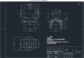
转向节的零件图如图2.1所示。由零件图可知,转向节是由上方的的叉形部件和下方的空心圆柱体所组成,且转向节为轴对称图形,相对来说比较简易。在模锻时,坯料横放在叉口上,先弯曲变形,后靠压入变形充填模膛。由转向节的结构可以初步得出,在锻造成形过程中,该锻件的叉形部分顶端以及空心圆柱底端的地方模膛较深,金属较难充满,这是由于坯料受弯曲和压入时,不容易充填到该模膛深处。因此在设计预锻模膛时必须保证此处能储备足够的金属,以便终锻时充满模膛。
技术要求:
①模锻斜度为7°;
②表面不应该有未充满、分层、裂纹、毛刺、氧化皮及腐蚀现象;
③硬度:HB207-241;
④纤维方向应与转向节外轮廓形状相符;零件材料:45#;零件名称:转向节;
⑤金相组织应为均匀的细晶结构。
[资料来源:https://www.doc163.com]


 [版权所有:http://DOC163.com]
目录
第一章 绪论 1
1.1 目的及意义 1
1.2 国内外的研究现状分析 1
1.3 研究内容 2
第二章 转向节零件的分析 4
第三章 热模锻压力机用锻模 5
3.1热模锻压力机模锻的特点 5
3.2热模锻压力机模锻件的分类及模锻工序的选择 5
3.3热模锻压力机吨位的确定 6
第四章 转向节的锻模设计 7
4.1锻件图的制定 7
4.1.1 确定分模面位置 7
4.1.2模锻件公差和余量 8
4.1.3模锻斜度 10
4.1.4 圆角半径 11
4.1.5 锻件图的技术条件 11
4.2 计算锻件的主要参数 12
4.3终锻模膛设计 13
4.3.1热锻件图的制定 13
4.3.2飞边槽设计 15
4.3.3钳口设计 17
4.3.4排气孔设计 17
4.4预锻模膛设计 18
4.5 毛坯尺寸的确定 19
4.6 制坯模膛的设计 21
第五章 热模锻压力机锻模结构设计 22
5.1 模架结构形式 22
5.2 模块设计 22
5.3锁扣设计 23
5.4 顶料装置设计 24
第六章 总结 29
参考文献 30
附录 31
致谢 34 [资料来源:www.doc163.com]
上一篇:铰链零件级进模具设计及数值模拟仿真(含CAD零件图装配图,UG三维图)
