臂部采用连杆机构的工业机械手设计
摘 要
本设计为了满足设计任务书的有关要求,设计开发了臂部采用连杆机构的工业机械手。论文对机械传动系统及液压缸的关键技术进行了分析。
文中介绍了工业机械手的历史与现状,分析和比较了工业机械手的各种传动方式及其优缺点,探讨了工业机械手的发展方向与趋势和臂部采用连杆驱动的工业机械手的可行性与实用性。其中,根据外界负载及各种条件计算并确定出了液压驱动系统中液压缸的各种参数,并对一些关键零件进行了强度校核。在实际计算说明过程中,根据给定的位置要求运用作图法对曲柄连杆中各连杆长度进行了精确的计算,并讨论了曲柄连杆机构与机械手运动轨迹的关系。同时,为提高设备整体的性能,对机械传动单元中重要部件的机械性能进行了计算,并采用作图法求出了臂部各连杆的长度,最后运用材料力学的分析方法对连接所采用部件的强度、刚度、稳定性进行了分析,保证了设备的总体精度,提高了设备的实用性,得到了比较理想的结果。
通过上述方法和措施,完成了臂部采用连杆机构的工业机械手的设计。
关键词:液压缸 ,连杆机构,齿轮齿条,工业机械手
ABSTRACT
In order to satisfy the requirements of design of the mandate, arm of the use of linkage of industrial machinery hand were designed and developmented in this paper. Papers on the mechanical drive system and hydraulic cylinders of key technologies were analyzed. [来源:http://Doc163.com]
In this paper, the development of history and current situation of industrial machinery hand were described, the various industrial machinery hand drive and their advantages and disadvantages were analysed and compared , the direction of development and trends of industrial machinery hands and the feasibility and practicality of a link-driven industrial machinery hand were discussed. Also, in accordance with the outside world load conditions and terms ,we determined the various parameters of hydraulic cylinders in a hydraulic drive system, and checked the strength of some key components . In practical terms that the process of calculation help, according to the given location of request we use mapping to calculate accurately the length of the connecting rod in the crank link and discussed the relationship of the crank linkage and the mechanical hand trajectory. At the same time, to improve the overall performance of equipment, the important components in mechanical transmission unit and the mechanical properties were calculated, we done a precise calculation on the linkage of the mechanical arm focusing on analytical method.At last,the Strength, stiffness and stability of connect the components used were analyzed by material mechanics,so we ensure that the overall accuracy of the equipment and enhance the usefulness of the equipment, gained more satisfactory results.
Through these methods and measures , the design of arm of the use of linkage of industrial machinery hand were completed.
Keywords:cylinder, linkage, gear, industrial machinery hand
设计要求
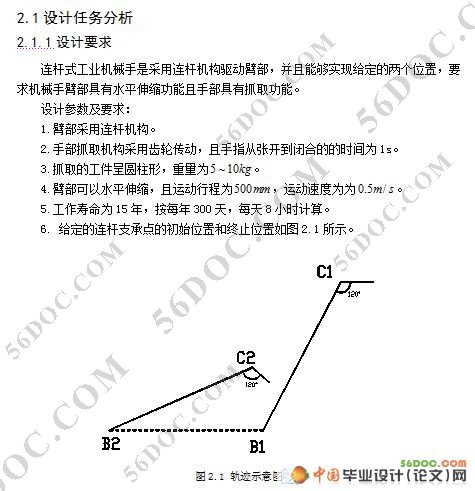
连杆式工业机械手是采用连杆机构驱动臂部,并且能够实现给定的两个位置,要求机械手臂部具有水平伸缩功能且手部具有抓取功能。
设计参数及要求:
1.臂部采用连杆机构。
2.手部抓取机构采用齿轮传动,且手指从张开到闭合的的时间为1s。
3.抓取的工件呈圆柱形,重量为 。
4.臂部可以水平伸缩,且运动行程为 ,运动速度为为 。
5.工作寿命为15年,按每年300天,每天8小时计算。
6. 给定的连杆支承点的初始位置和终止位置。
本次设计的内容由总体方案的设计、手部的设计、伸缩油缸的设计、连杆的设计及校核等四部分组成。根据整个设计过程可以得到如下结论:
1、总体方案的确定。针对本次连杆式机械手的设计提出了三种方案,经比较、分析各种方案的优缺点,最终确定第二种方案是最适合的。
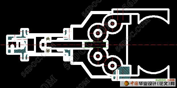
2、手部的设计。手部的设计主要包括液压缸的设计和手部传动齿轮的设计,在设计过程中,通过详细的计算,确定了齿轮及液压缸各部件具体参数,最后通过校核保证了这些部件都是满足要求的。 [资料来源:http://www.doc163.com]
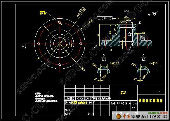
3、伸缩油缸的设计。本部分主要是对伸缩油缸的各个部件进行设计及选择,文中对缸筒、活塞及活塞杆等部件进行了计算,并确定了其基本参数,然后对某些部件进行强度校核及稳定性校核的计算,得到这些部件是满足要求的。
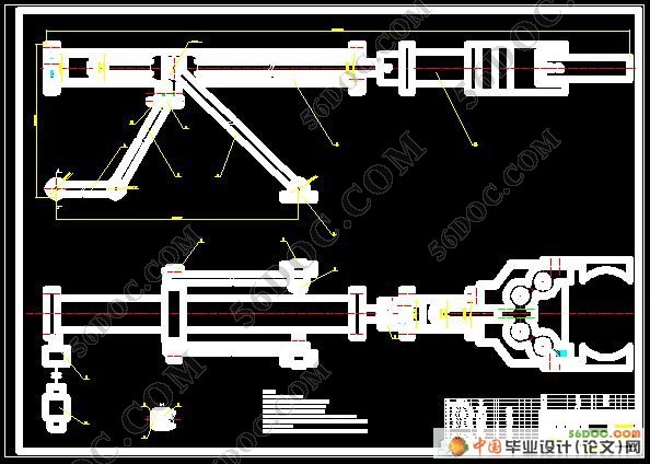
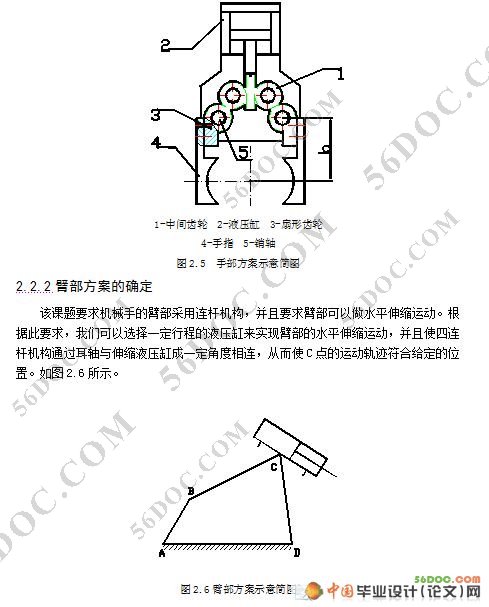
4、连杆机构的设计及校核。根据本次毕业设计课题的要求,臂部须采用连杆机构来完成工件位置的转移。文中根据给定的两个位置运用作图法求出了各连杆的长度,且同样对各连杆的强度及稳定性进行了校核计算,经计算及校核,得到各连杆均满足传动需求,可以顺利完成作业。
 [资料来源:Doc163.com]

目 录 13000字
第1章 绪论 1
1.1 课题的来源及研究意义 1
1.2 工业机械手的应用现状及发展方向 1
1.3 臂部采用连杆机构的工业机械手的优点 2
第2章 总体方案的设计 3 [资料来源:https://www.doc163.com]
2.1 设计任务分析 3
2.1.1 设计要求 3
2.1.2 任务分析 3
2.2 总体方案的确定 4
2.2.1 手部方案的确定 4
2.2.2臂部方案的确定 6
第3章 手部的设计 7
3.1 确定手部结构 7
3.2 手指夹紧力的计算 7
3.3 手部结构驱动力的计算 7
3.4 传动齿轮的设计及校核 7
3.4.1 确定齿轮的材料、热处理方法及等级精度 8
3.4.2 按齿面的接触疲劳强度设计齿轮 8
3.4.3 齿根的校核 9
3.4.4 计算齿轮的主要几何尺寸 10
3.4.5绘制齿轮的零件图 10
3.5 液压缸的设计与计算 11
3.5.1 计算活塞杆的驱动力 11
3.5.2 确定液压缸的安装形式 11 [资料来源:http://Doc163.com]
3.5.3 确定端盖与缸筒的结构及其连接方式 11
3.5.4 确定液压缸的基本参数 11
第4章 臂部的设计 16
4.1 连杆机构的选择 16
4.2 驱动力的计算 16
4.3 液压缸的设计与计算 17
4.3.1确定液压缸的安装形式 17
4.3.2确定端盖与缸筒的结构及其连接方式 17
4.3.3 确定液压缸的基本参数 17
4.4 连杆长度的计算及校核 21
4.4.1 作图法求连杆长度 21
4.4.2 校核连杆强度 23
第5章 电机及减速器的选择 29
5.1 电动机的选择 29
5.2 减速器的选择 29
结论 30
参考文献 31
致谢 32
附录 图纸列表
上一篇:潜水泵泵盖试压机试验台的设计(CAXA+PROE三维造型)☆
下一篇:臂部采用凸轮的工业机械手设计
