
三自由度机械手腕机械系统设计(含Pro/E三维图)
三自由度机械手腕机械系统设计(含Pro/E三维图)(任务书,开题报告,论文说明书9000字,,Pro/E三维图)
摘 要
在工业上,机器人有广泛的应用,尤其是在高温,高压,粉尘,噪音,以及带有放射性和污染的场合。而工业机器人是相对较新的电子设备,它正开始改变现代化工业面貌。手腕是连接末端执行器和手臂的关键,是联接手部与臂部的部件,它的作用是调整或改变工件的方位。本设计为三自由度工业机器人手腕,可以在两个方向上旋转在一个方向上弯转。三维造型采用的造型软件为Pro/ENGINEER, Pro/ENGINEER Wildfire野火版2.0,其易学易用、功能强大和互连互通的特点,推动了整个产品开发机构中个人效率和过程效率的提高。它既能节省时间和成本,又能提高产品质量。本文是对整个设计工作和造型过程较全面的介绍和总结。
关键词: 工业机器人, 三自由度, 机器人手腕.
Abstract
Industrially, Industrial robots are found in numerous applications, especially in the place where high temperature, high pressure, dust, noises, radioativity and infectant. Industrial robots are relatively new electromechanical devices that are beginning to change the appearance of modern industry. Wrist is the key of elemet which connect arm and final implement. Adjust the workpiece is its function. This scheme introduced a industrial robot wrist with three degree of freedom. It is composed of one bend axis and two rotary axes. Use Pro/ENGINEER Wildfire drawing 3D model. The software that the 3D shape adopt is Pro/ENGINEER, the Pro/ENGINEER Wildfire version 2.0 with it easy to learn easily use of characteristics, pushed the exaltation of personal efficiency and the process efficiency in the whole product development organization. It since can save time and cost and then raise product quality. This paper is more comprehensive introduction and summing-up for the for the whole design work and the drawing of 3D model.
[来源:http://www.doc163.com]
KeyWords:Industrial robot, three degrees of freedom, robot wrist.
[资料来源:http://doc163.com]
目 录
摘 要 1
Abstract 2
1 绪论 5
1.1机器人定义 5
1.2 工业机器手简介 5
1.3机器人的组成 6
1.4驱动装置 6
[资料来源:http://Doc163.com]
1.5控制系统 6
1.6执行机构 7
2 工业机器人手腕的总体设计 8
2.1机器人手腕设计概述 8
2.2机器人腕部的结构特点 9
2.2.1单自由度手腕 9
2.2.2二自由度手腕 10
2.2.3三自由度手腕 11
2.3设计要求 13
3控制系统 14
3.1选择电机 14
3.2 PLC编程 14
4锥齿轮设计 18
4.1锥齿轮的设计计算 18
4.2齿面接触疲劳强度计算 18
4.3齿根弯曲疲劳强度验算 19
4.4 主要几何尺寸计算 19
5. 同步带传动设计 20
5.1 设计功率 20
5.2 带轮的基本尺寸 21
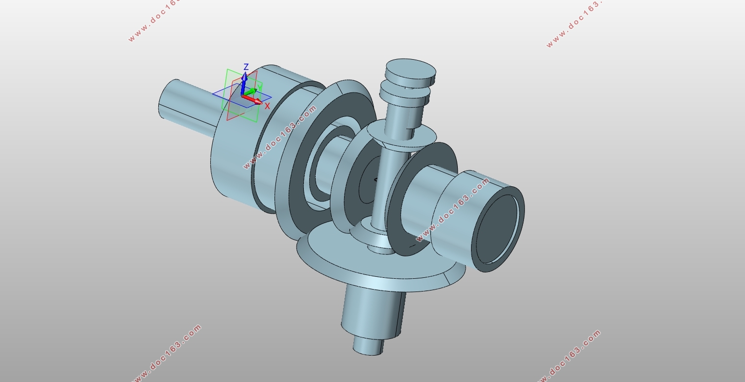
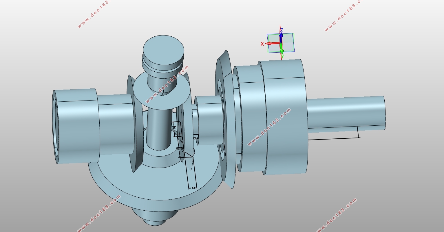
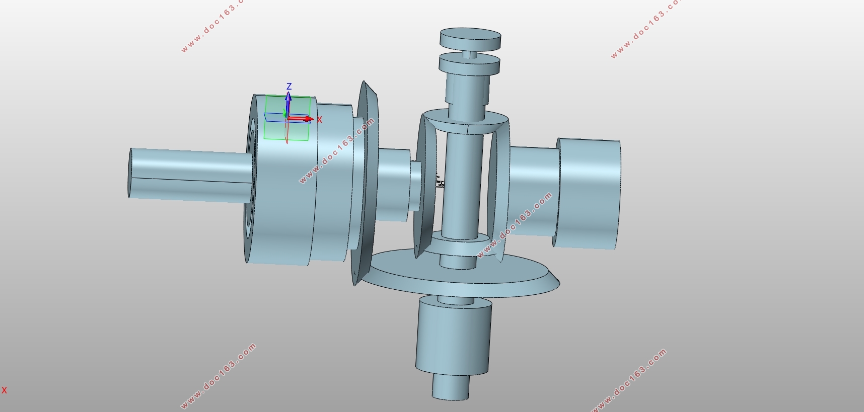
6 三维造型的绘制 22
6.1 造型软件简介 22
6.2典型零件的绘制 25
结 论 49
致谢 50
参考文献 51
[资料来源:https://www.doc163.com]
下一篇:高精度三轴运动平台设计及控制(含CAD零件图装配图)