10t四连杆门座起重机设计及运行机构设计(含CAD图,CREO三维图)
10t四连杆门座起重机设计及运行机构设计(含CAD图,CREO三维图)(任务书,开题报告,外文翻译,文献检索,论文说明书12000字,CAD图4张,CREO三维图)
摘要
本次设计以MQ1035四连杆门座起重机为例,简单的叙述了课题的研究目的及其意义。结合所学专业知识,讲述了门座起重机的总体设计步骤,对MQ1035四连杆门座起重机进行了总体设计计算、运行机构设计计算、cad图纸绘制以及三维仿真建模。在设计中,对水平位移补偿系统及臂架自重平衡系统、整机的抗倾覆稳定性进行了校核验算。电机、减速器、制动器的选用也符合使用要求。
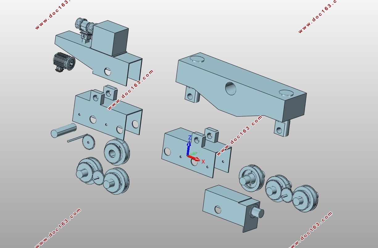
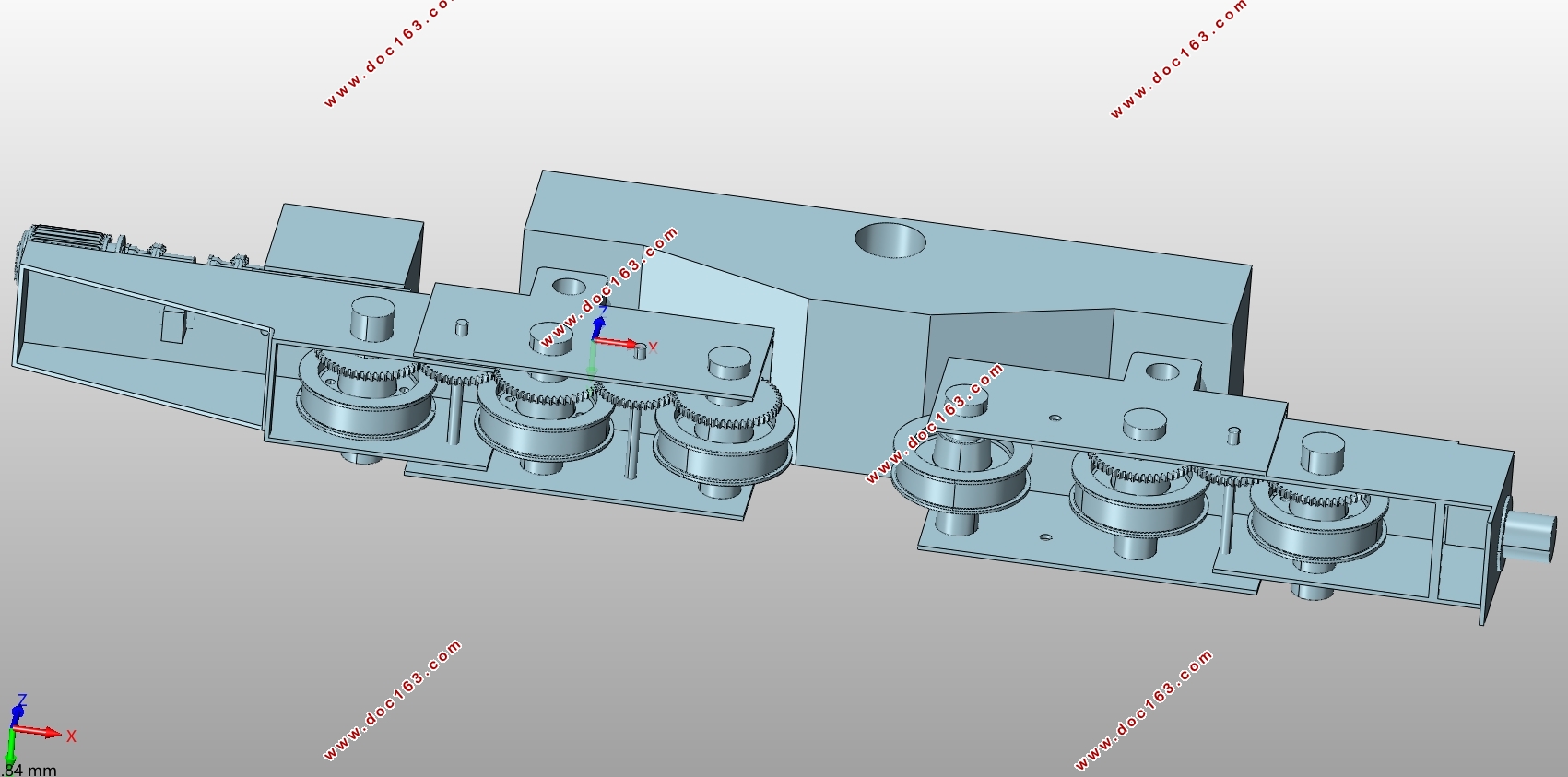
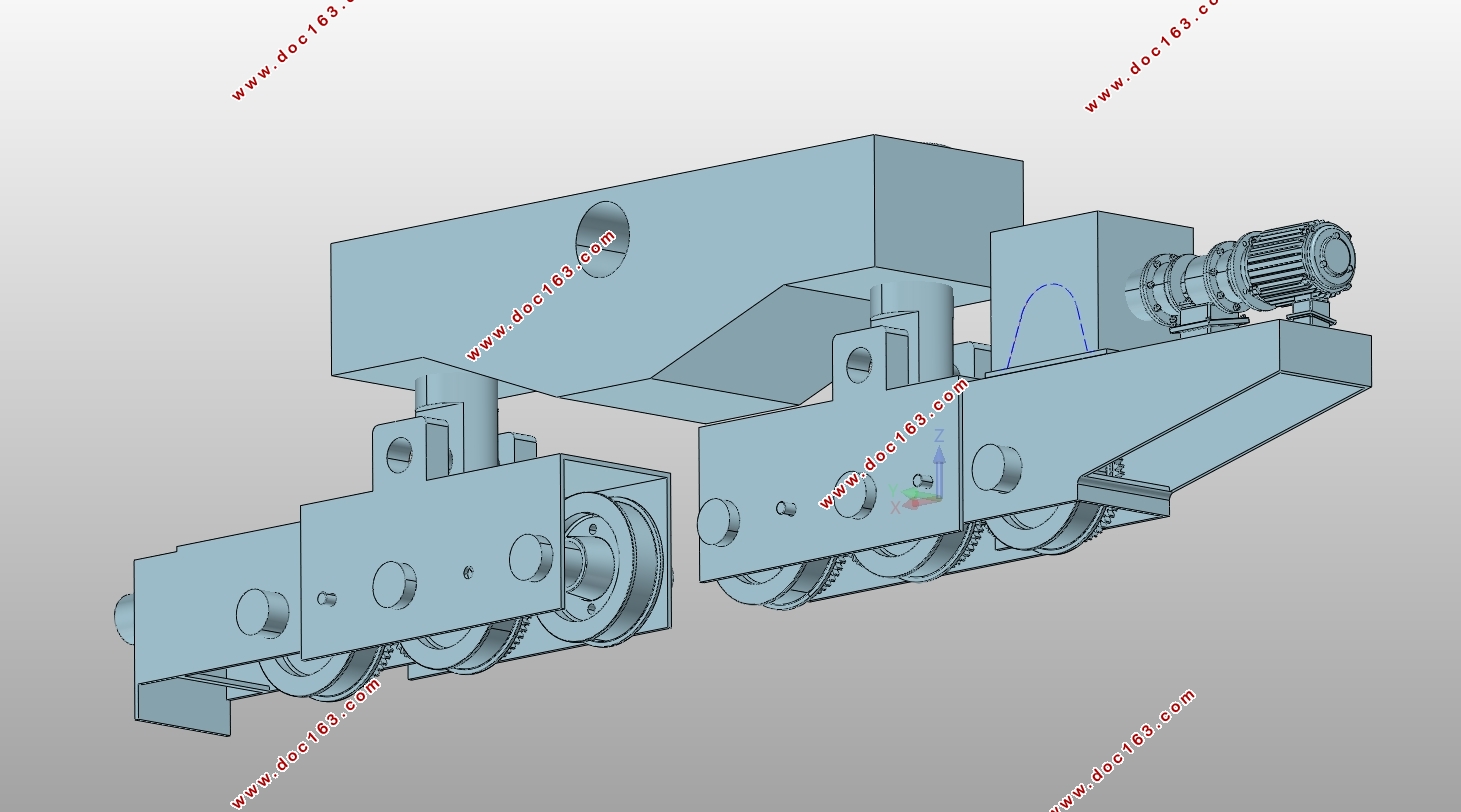
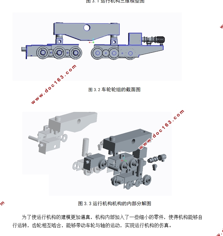
本次课题的特色在于借助三维建模软件creo建立起重机的模型,并将整机导入Adams进行模拟仿真,实现了整机装配过程以及正常工作的运动仿真,从而得到更为精确的性能参数,对起重机进行设计改进。文章中主要介绍了运行机构的设计以及建模。
关键词:四连杆、门座起重机、总体设计、三维建模
Abstract
This design takes the MQ1035 four link gantry crane as an example, briefly describes the purpose and significance of researching the topic. Combined with the professional knowledge to introduces the general design steps of portal crane, the MQ1035 four link portal crane for the overall design calculation, calculation and operation mechanism design CAD drawings and 3D modeling. In this design, the compensation system of horizontal displacement and the boom of gravity balance system, the whole antioverturning stability is carried out to calculate the calibration verification. The choice of motor, reducer, brake also meet the requirements of the use.
Features of this issue is by means of three-dimensional modeling software creo to build the crane model and the whole portal crane is introduced into Adams to carry out simulation. Realized the whole process of assembly and motion simulation of normal work, resulting in more accurate performance parameters for crane design improvements. This article mainly introduces the design and modeling of the crane operating mechanism.
Key words: four link, gantry crane, overall design, three-dimensional modeling
1.2课题研究的主要内容
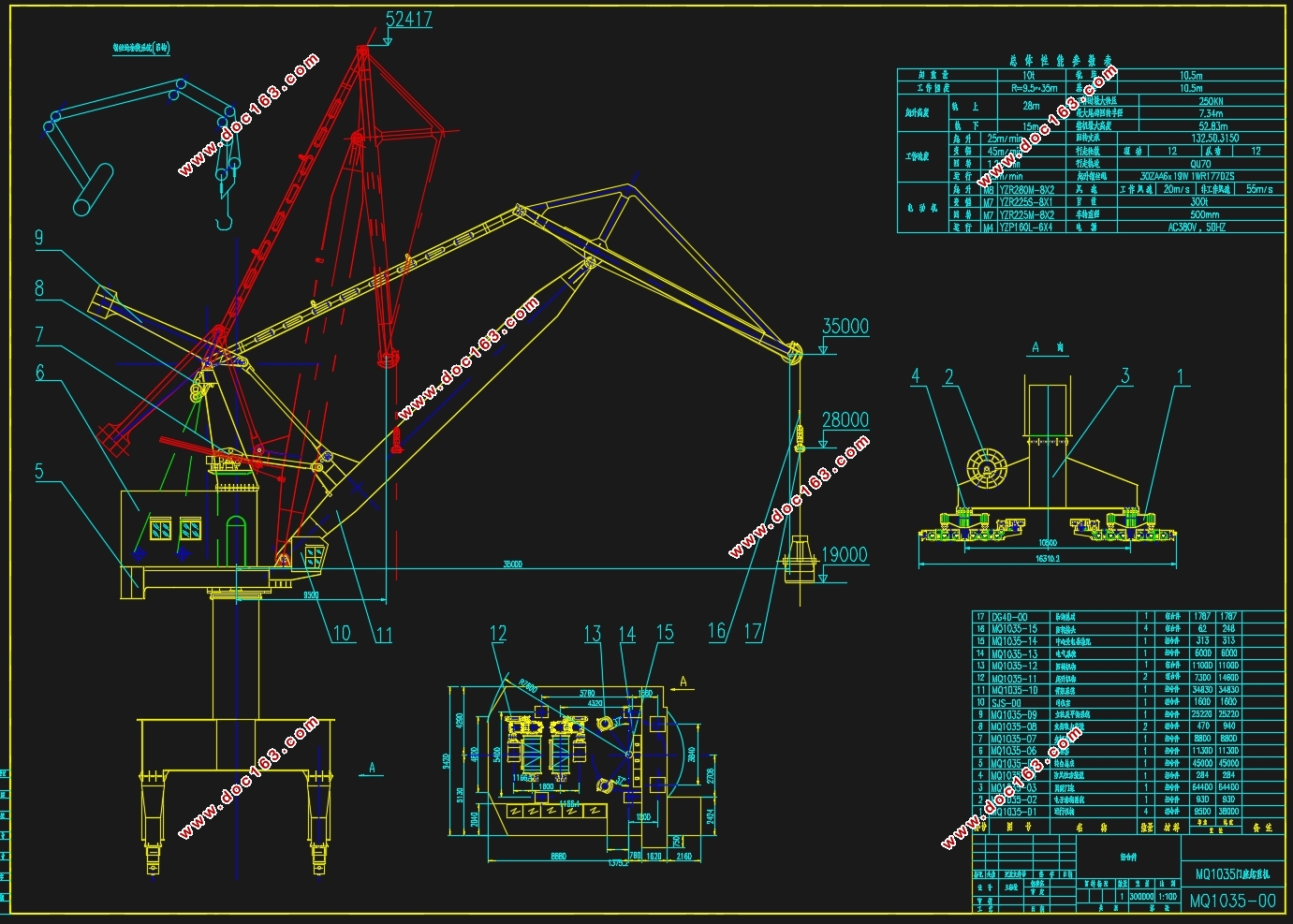
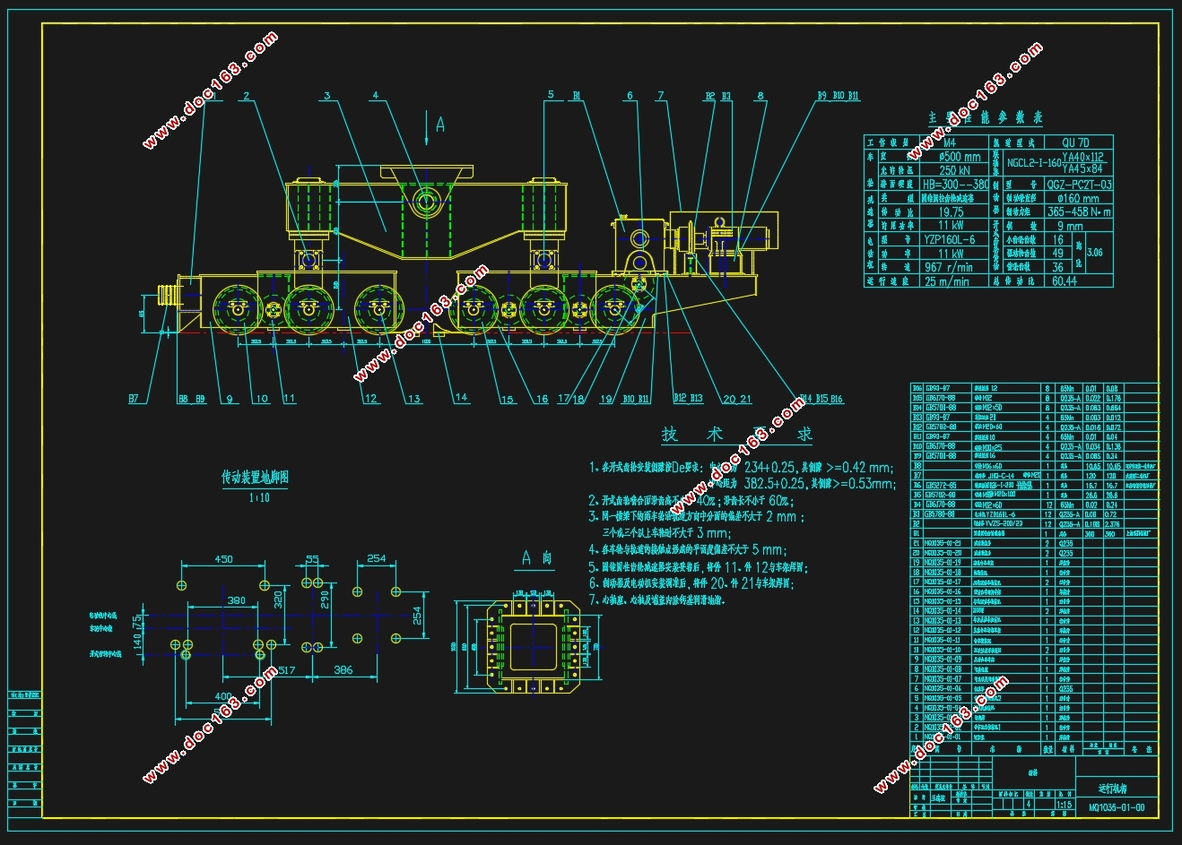
这次的课题是以MQ1035型的门座起重机作为对象进行研究,根据给定的基本参数并且参照相关的设计手册,进行整机的总体设计验算、运行机构设计计算及三维仿真建模,这个过程中,需要我们完成:首先,我们要确定运行机构的设计方案,然后完成电动机、减速器、联轴器等设备的选型,最后根据选型的结果,对其进行校核验算,完成运行机构的设计部分,将数据导入creo软件中,进行运行机构的三维仿真建模。
2.总体设计计算
2.1起重机主要参数
在进行初步设计时,我们需要根据需求,来确定技术参数。此次设计的MQ1035门机的参数表如下: [来源:http://Doc163.com]
表2.1 技术参数
项目名称 性能参数
起重量 10t
工作幅度 最大/最小 35/9.5
起升高度 最大/最小 28/15
机构工作速度 起升机构 25m/min
变幅机构 40m/min
回转机构 1.2r/min
运行机构 25m/min
机构工作级别 整机 A8
起升机构 M8
变幅机构 M7
回转机构 M7
运行机构 25m/min
基距/轨距 10.5/10.5
风速 工作最大风速 20m/min
非工作最大风速 55m/min
许用轮压 250KN
轨道型号 QU70 [资料来源:www.doc163.com]
电源 380V/50HZ
[资料来源:http://doc163.com]
 [资料来源:www.doc163.com]

目录
摘要 2
Abstract 2
1绪论 3
1.1课题研究的目的和意义 3
1.2课题研究的主要内容 3
2.总体设计计算 3
2.1起重机主要参数 3
2.2 四连杆臂架结构的尺寸: 4
2.3 货物水平位移补偿系统设计 5
2.3.2组合臂架方案的优化 6
2.4臂架自重平衡系统的设计 11
2.5载荷计算以及载荷组合 14
2.6整机稳定性校核 23
2.7 轮压计算 28
3运行机构整体方案的设计 30
3.1.运行机构计算 31
3.2运行机构三维建模 37
3.4本章小结: 38
4.工作总结 39
参考文献 39
致谢 40
[资料来源:http://doc163.com]
上一篇:行星齿轮减速器参数化系统设计与开发(含SolidWorks三维图,程序)
下一篇:铸件搬运机械手结构及液压控制系统设计(含CAD零件图装配图)
