离合器壳体T2面孔钻削加工工艺装备设计(含CAD图)

离合器壳体T2面孔钻削加工工艺装备设计(含CAD图)(任务书,开题报告,外文翻译,设计说明书12000字,CAD图纸4张)
摘 要
离合器是在汽车中不可缺少的部件之一,处于发动机与变速箱两者之间,其壳体主要起安装离合器与连接前后发动机与变速箱的作用。离合器壳体加工质量的好坏会直接影响到整个汽车的工作性能。其加工机床为组合机床,是一种以专业的部件为基础,来加工四个特定安装孔的一种半自动卧式钻孔机床。在工业化快速发展和设计制造各种化学装置的过程中,组合机床越来越被广泛使用,越来越多地转向生产力。
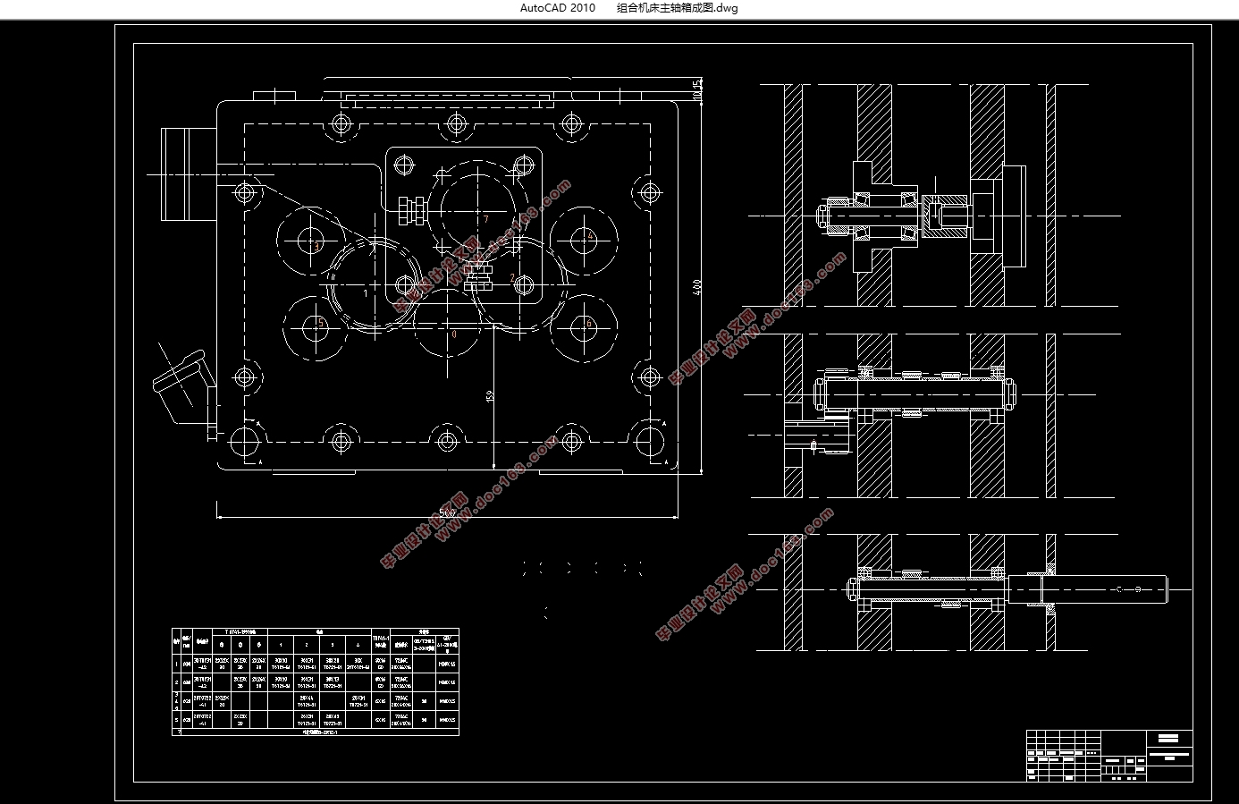
本论文的主要任务是对给定离合器壳体的零件图,对其T2面的安装孔进行工艺分析,并进行加工此道工序的组合机床以及主轴箱的相关设计。本文设计主轴箱通过动力箱驱动轴传入动力,再以齿轮传动进而将动力传到输出轴,配以润滑油泵进行润滑,工件通过皮带传送到加工位置后进行定位夹紧,从而达到此道工序的加工目的。
关键词:离合器壳体、组合机床、主轴箱
Abstract
The clutch is one of the indispensable components in the car. It is located between the engine and the gearbox. The housing is mainly used to install the clutch, which is connected to the front and rear to act as a gearbox. The quality of the clutch housing can directly affect the performance of the entire car. The machine tool is a combination machine tool, which is a semi-automatic horizontal drilling machine based on professional components to machine four specific mounting holes.
In the rapid development of industrialization and the design and manufacture of various chemical devices, combined machine tools are becoming more and more widely used, and more and more turning to productivity.The main task of this thesis is to analyze the parts of a given clutch housing, analyze the process of the mounting holes on the T2 surface, and design the combined machine tool and the headstock for the processing of this process. In this paper, thespindle box is designed to transmit power through the power box drive shaft, and then the gear transmission is used to transmit the power to the output shaft, which is lubricated with a lubricating oil pump. The workpiece is conveyed to the machining position through the belt and then positioned and clamped to achieve this process,This is the Processing purpose.
Keywords: clutch housing, combined machine tool, headsto
[资料来源:http://Doc163.com]


目录
第1章 绪论 1
1.1 研究目的 1
1.2 组合机床国内外发展现状 1
1.3组合机床的发展趋势 2
1.4研究基本内容以及技术方案 3
1.4.1零件分析以及工艺方案 3
1.4.2组合机床的相关设计与主轴箱设计 4
第2章 离合器研究方法及选材 5
2.1离合器原理 5
2.2壳体的分析 5
2.2零件的选材 6
第3章 离合器壳体工艺路线设计 7
3.1工艺路线分析 7
3.1.1加工阶段划分 7
3.1.2加工顺序确定 7
3.1.3辅助工序 7
3.1.4定位基准选取 7
3.1.5加工方法选取 8
3.2离合器工艺路线设计 8
第4章 组合机床设计 10
4.1拟定方案 10
4.2三图一卡的设计 11
4.2.1零件工序图的设计 11
4.2.2加工示意图的设计 11
4.2.3机床联系尺寸图设计 14
4.2.4生产率计算卡 16
第5章 主轴箱设计 17
5.1绘制主轴箱原始设计图 17
[资料来源:http://Doc163.com]
5.2设计传动系统 17
5.3主轴箱主要尺寸的设计 19
4.4检验 22
第6章 结论 23
参考文献 24
致谢 26
[资料来源:www.doc163.com]
下一篇:转向臂轴参数化设计与有限元分析
