变速箱箱体底面铣削加工工艺装备设计(含CAD夹具图,工艺卡工序图)

变速箱箱体底面铣削加工工艺装备设计(含CAD夹具图,工艺卡工序图)(任务书,开题报告,论文说明书13000字,CAD图纸8张,工艺卡工序图)
摘要
犁刀变速箱箱体零件是旋耕机的一个重要的机械装置,在工厂大批量生产的情况下,要为其设计出专用的生产线,以保证加工质量和生产效率。本次工艺装备设计便是针对犁刀变速箱的底面铣削加工工艺设计出组合机床和专用夹具。
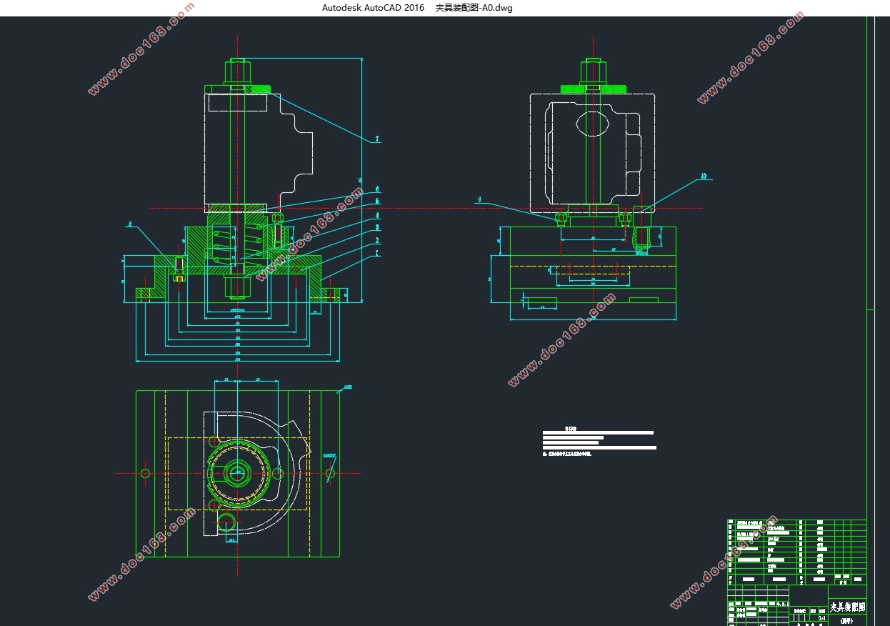
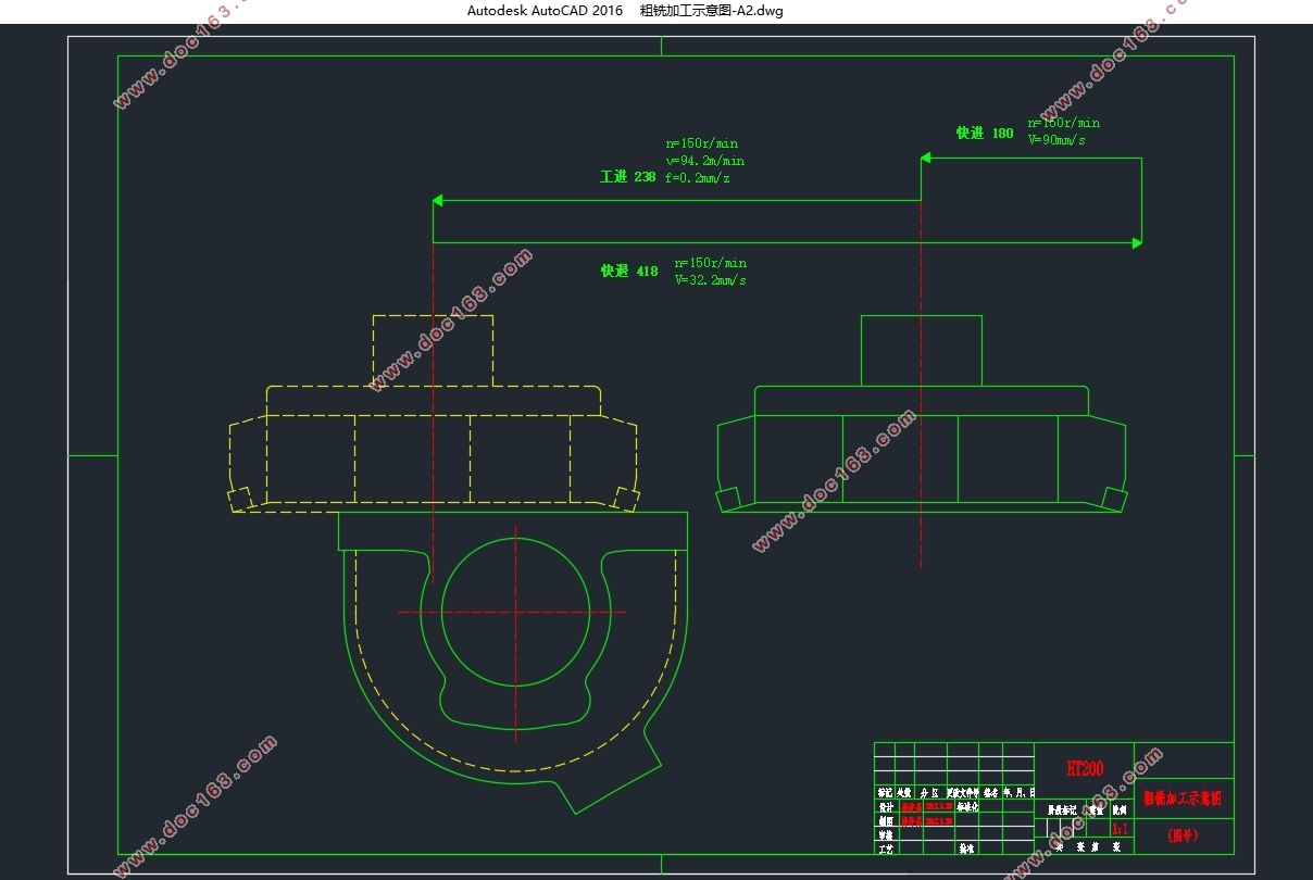
编写本设计说明书时,参考了大量的机械工艺手册,详细分析了犁刀变速箱的工艺结构,结合实际生产情况,编制犁刀变速箱的加工工艺路线,并计算加工参数,在此基础上设计了工件的总体加工方案,分别设计粗、半精铣的组合机床,并绘制组合机床设计的三图一卡,设计底面铣削工艺的随行夹具。详细介绍了随行夹具的组成结构和工作原理,并通过加工参数计算校核随行夹具的结构设计及部件选择是否合理。
关键词:工艺规程组合机床 随行夹具
Abstract
Coulter gear-box parts of rotary cultivator is an important mechanical device, under the condition of mass production in the factory, to aspecial for the design of the production line, to ensure the processing quality and production efficiency. This technology is designed to design the combination machine tool andspecial fixture for the ground milling process of the gearbox. [资料来源:https://www.doc163.com]
When writing the design specification, refer to a lot of manual mechanical process, process structure of coulter gearbox are analyzed in detail, combined with the actual production conditions, preparation of the processing technology of the colter transmission routes, and calculate the processing parameters, on the basis of the design overall processing of the workpiece, respectively, design a combination of coarse and fine milling machine, combination machine tool design and draw three figure a card, pallet design bottom milling process. The structure and working principle of the accompanying fixture are introduced in detail, and it is reasonable to calculate the structure design and the selection of the parts.
Key Words:technological procedure;combined machine tool;follow fixture
2.1 零件的工艺分析
由零件图纸得知变速箱的材料为HT200。
该零件上的主要加工面为底面N、两侧面M和P、凸台面、2-Φ80H7孔和球Φ30H9孔。
变速箱箱体底面的平面度为0.05mm,影响旋耕机动力轴与拖拉机变速箱输出轴的连接定位和箱体密封。该底面同箱体两侧面2-Φ80H7孔的中心连线的平行度为0.07mm,两侧面2-Φ80H7孔的中心连线与两侧面M和P的垂直度均为0.1mm。
2.2 确定零件毛坯尺寸
该零件为轻型大批量生产零件,毛坯为铸件,砂型造型。零件基本面N面、M面、P面和2-Φ80基本空均为铸造出型。
参考资料书《实用机械加工工艺手册》表3-13,取该铸件尺寸公差等级为CT10级,取加工余量等级MA为G级[1],根据表3-9和3-12,选择该零件加工余量为4mm[2]。
[资料来源:http://doc163.com]


目录
第1章绪论 1
组合机床 1
国内外现状 1
发展趋势 2
随行夹具 2
国内外现状 2
发展趋势 2
课题研究内容与目标 3
第2章箱体零件加工的工艺规程制订 4
2.1 零件的工艺分析 4
2.2 确定零件毛坯尺寸 5
2.3 拟定零件工艺路线 5
2.3.1 工艺方法的确定 5
2.3.2 确定工艺过程方案 5
2.4 选择加工设备与工艺装备 7
2.4.1 选择加工机床 7
2.4.2 选择工序夹具 8
2.4.3 选择刀具 8
2.5 铣削参数计算 8
2.5.1 工序020(粗铣N基准面至47mm)铣削参数计算 8
2.5.2 工序030(半精铣N基准面至46±0.05mm)铣削参数计算 10
2.6 生产节拍计算 11
[资料来源:https://www.doc163.com]
第3章组合机床总体设计 12
3.1 被加工零件工序图 12
3.2 加工示意图 13
3.3 机床联系尺寸图 14
3.3.1 选择主运动动力部件 14
3.3.2 选择进给运动部件 14
3.3.3 选择滑台侧底座 15
3.3.4 设计加工工作台 15
3.3.5 设计各组件联系尺寸 15
3.4 机床生产率计算卡 15
3.4.1 理想生产率Q 15
3.4.2 实际生产率Q1 16
3.4.3 机床负荷率η负 16
第4章随行夹具设计 17
4.1 制订零件的定位夹紧方案 17
4.2 夹具结构设计 18
4.3 夹具受力分析 19
4.4 定位精度分析 20
结论 22
参考文献 23
致谢 24
附录 25
附A:机械加工工艺过程卡片 25 [资料来源:http://www.doc163.com]
附B:粗铣加工工序图 26
附C:半精铣加工工序图 27
附D:粗铣机床生产率计算卡 28
附E:半精铣机床生产率计算卡 28
上一篇:汽车转向节主销孔镗削加工工艺装备设计(含CAD夹具图)
