十字轴机械加工工艺及钻6孔夹具设计(含CAD零件图装配图,工艺卡)

十字轴机械加工工艺及钻6孔夹具设计(含CAD零件图装配图,工艺卡)(任务书,说明书5000字,CAD图纸6张,工艺卡)
摘 要
这次设计的是十字轴机械加工工艺规程及工艺装备设计,包括零件图、毛坯图、装配图各一张,机械加工工艺过程卡片和与工序卡片各一张。首先我们要熟悉零件和了解其作用,它位于车床变速机构中,主要起换档作用。然后,根据零件的性质和零件图上各端面的粗糙度确定毛坯的尺寸和械加工余量。最后拟定拨差的工艺路线图,制定该工件的夹紧方案,
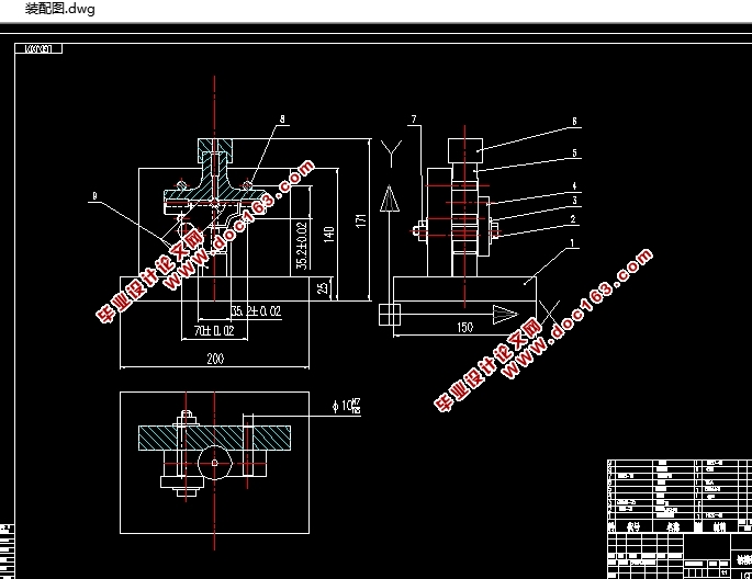
画出夹具装配图。
就我个人而言,我希望能通过这次课程设计,了解并认识一般机器零件的生产工艺过程,巩固和加深已学过的技术基础课和专业课的知识,理论联系实际,从中锻炼自己分析问题、解决问题的能力,为今后的工作打下一个良好的基础,并且为后续课程的学习打好基础。
Abstract
This time I design the lathes of the shift forks CA6140(831005), including that the part pursuing , the blank pursues , assembling pursues , the machine work procedure card the working procedure card every sheet .We should know the part very well and know its effect first , it is worked in the organization which is used for change the speed in a lathe, and the mainly role of the part is alter the speed. Then, we design the dimension of the blank and instrument process a margin of the part according to part character and the harshness of each face .Finally, I design the handicrafts route picture of the shift forks, work out the fastening motion scheme being workpiece's turn , draw up clamp assembling picture. [资料来源:http://doc163.com]
As far as my individual be concerned, I want to knowing the general productive technology of machine part , consolidating and deepening the knowledge of basic course and specialized course what I have already learned , integrates theory with practice, and improve the
ability to solve problems, what’s more , striking the basis for the future work and the following course’s studying .
一、零件的工艺分析
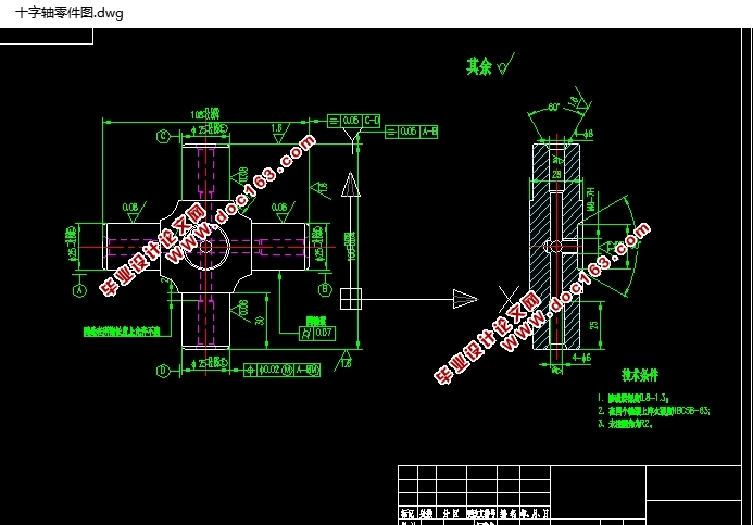
零件的材料为 20GrMoTi, 需要模锻, 模锻性能优良, 工艺较复杂 ,但尺寸精确,加工余量少,为此以下是十字轴需要加工的表面以及加工表面之间的位置要求:
1、 四处Φ25外圆及四个Φ8、Φ4的内孔、
2、右端面Φ50×60°内孔及M8丝孔。
3、Φ25外圆的同轴度为0.007,位置度为Φ0.02,两端的对称度均为0.05.
由上面分析可知,可以先上四爪卡盘粗车,然后上弯板采用专用夹具压紧、找正进行加工,并且保证形位公差精度要求。 并且此 零件没有复杂的加工曲面,所以根据上述技术要求采用常规的加工工艺均可保证。 [资料来源:www.doc163.com]
[资料来源:http://doc163.com]


目录
一、零件的工艺分析 1
二.机械加工工艺设计 2
1、确定生产类型 2
2、确定毛坯 2
2.1、确定毛坯种类: 2
2.2、确定锻件加工余量及形状: 2
三、工艺规程设计 4
3.1选择定位基准: 4
3.2制定工艺路线: 4
3.3表面加工方法的确定 5
3.4加工阶段的划分 5
3.5工序顺序的安排 5
3.6确定工艺路线 6
四.机械加工余量、工序尺寸及公差的确定 7
4.1 钻铰Φ8丝孔 的工序尺寸 7
4.1.1.钻Φ5丝孔,以φ25轴线为基准。 7
4.2.2 钻孔工步 7
4.3时间定额的计算: 7
4.4 其它时间计算 8
五、夹具设计 9
5.1夹具选择 9
5.1.1问题的提出 9
5.1.2夹具设计 10
5.2、定位误差分析 10
5.3、夹具设计及操作的简要说明 11
六.参考文献 12 [资料来源:http://www.doc163.com]
上一篇:连杆体的机械加工工艺规程的编制(含CAD零件图装配图,工艺卡)
