恒流式直流电子负载器的设计

资料介绍:
恒流式直流电子负载器的设计(任务书,开题报告,外文翻译,论文11000字)
摘要
随着电子科技不断的更新发展,人们对电源设备的要求愈来愈高,使得原有的电源检测技术已经不能满足现在的检测要求。相比于传统检测方法,使用电子负载能够使负载两端的电压检测的更加精准,负载电流的调整也能够做到十分精细的地步。电子负载的工作方式多种多样,例如恒流,恒压,恒阻和恒功率等方式。本文探究了恒流部分,方案中采用了STC89C52 单片机作为电路的核心控制,以DAC7811为基础设计了的电路的控制电路,电流采样电路使用ADC0832单片机为核心。实验使用了运算放大器来放大信号,使用 PI调节器和负反馈控制环路等来改变MOSFET的栅极电压是整个实验电路的核心内容。MOS管在实验方案中不仅被用作待测电源的负载,同时也被用作电路电流的控制元件。采样电路采得电压信号以后通过AD模块输入单片机与预设值进行比较,单片机输出信号控制MOS管导通量的大小,使MOS管的内阻发生相应的变化,最终通过以上操作使流过负载的电流保持恒定,实现恒流的目的。
关键词:电源检测 电子负载 反馈 MOS管
The design of Constant flow dc electronic
ABSTRACT
[版权所有:http://DOC163.com]
Along with the development of the electronic power technology, people has higher requirement for the power equipment. The traditional power test technology is faced with enormous challenges. After considering all aspects of objective factors, in this scheme adopted the STC89C52 single-chip computer as core control circuit, on the basis of the DAC7811 design the circuit of the control circuit, using the ADC0832 single-chip microcomputer as the core of current and voltage sampling circuit. PI regulator, negative feedback control loop to control the grid voltage of MOSFET. MOS tube in experimental scheme is not only used as power supply under test load, at the same time is also used as a current control element. Signals to be picked by AD sampling circuit module input microcontroller compared with preset value, and then through the single chip microcomputer to control the MOS tube guide flux, which changes its internal resistance, to maintain a constant current through the load, achieve the goal of constant current.
[来源:http://Doc163.com]
Keywords:Power test Electronic load Feedback MOS tube
[资料来源:http://doc163.com]


目录
摘要 I
ABSTRACT II
第一章 绪论 1
1.1 电子负载的意义 1
1.2 电子负载工作原理 2
第二章 系统方案论证与硬件设计 3
2.1设计要求 3
2.2 方案论证 3
[资料来源:http://Doc163.com]
2.2.1 总体方案选择 3
2.2.2 核心处理器的选择 6
2.2.3显示模块的选择 7
2.2.4键盘模块的选择 8
2.2.5 D/A转换模块DAC7811 9
2.2.6采样电路模块 9
2.2.7电子模拟负载的方式 10
2.2.8功率耗散MOS管的选型. 11
2.2.9 PI调节器 12
2.2.10 电源设计 13
第三章 软件设计 15
3.1 电压电流A/D采样程序设计 16
3.2 液晶显示子程序 16
3.3 D/A转化程序 17
3.4 键盘识别处理程序设计 18
第四章 系统调试 20
4.1 硬件调试 20
4.2 软件调试 21
第五章 总结结论 22
参考文献 23
致谢 25
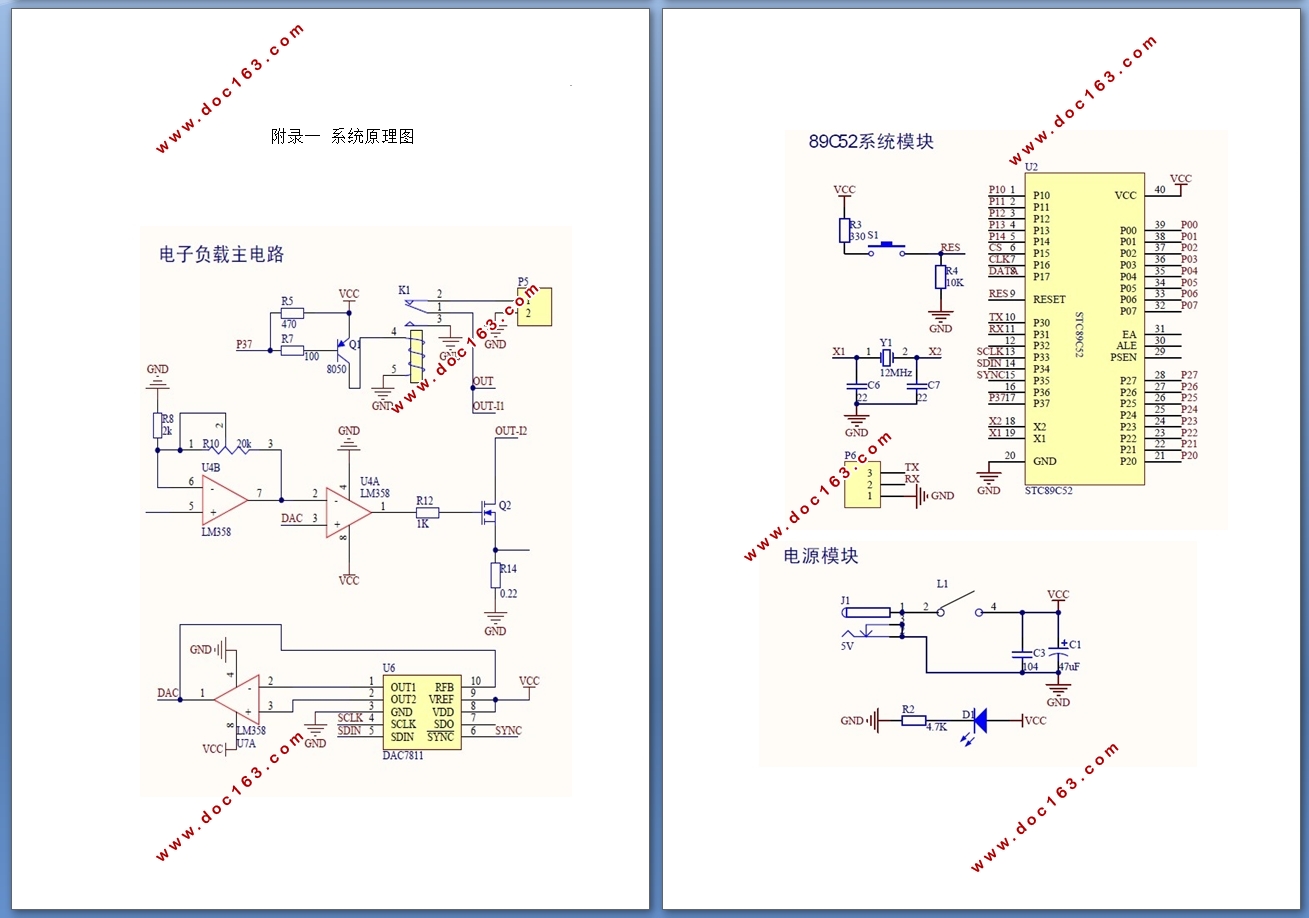
附录一 系统原理图 26 [资料来源:www.doc163.com]
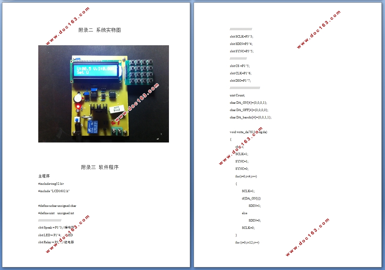
附录二 系统实物图 30
附录三 软件程序 30 [版权所有:http://DOC163.com]
