
数控直流稳压电源的设计(附电路原理图,PCB图)
数控直流稳压电源的设计(附电路原理图,PCB图)(任务书,开题报告,论文说明书14000字,电路原理图,PCB图)
摘 要
稳压电源可以为各类电子产品,电动装置、实验仪器等提供电能,是它们正常工作的基础,与人类的生产生活息息相关,所以具有非常重要的意义。
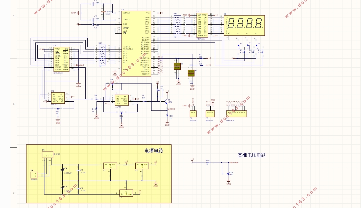
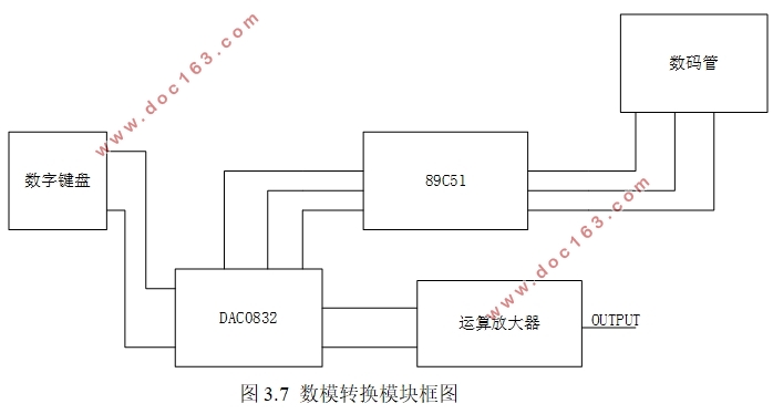
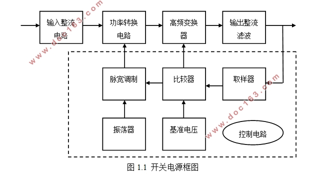
本文设计了一款数控电源。该数控电源,可以分成三个模块,分别是电源电路模块、基准电路模块、数模转换模块。其中,电源电路模块、基准电路模块给数模转换模块提供合适的工作电压。51单片机控制数/模转换器DAC0832的输出并将电压值显示在数码管上。利用UA741运算放大器将DAC0832的电流输出转变为电压输出。
本文设计的数控电源不仅可以输出0-12V,精度为0.1的直流稳定电压,还可0.1V步进。将测试输出电压与仿真输出电压对比分析可知,本文设计的数控电源在低电压范围内(0~4.5V),输出误差小于0.06V,实际输出电压与理想输出电压几乎一致,该电源系统表现较小的输出误差;在高电压范围内(4.5~12V),明显地看出,实际输出电压(黑色曲线)开始偏离理想输出电压,表现出较大的误差(0.06~0.1V)。因此,该电源系统在高电压范围内的误差值在允许范围内,该电源系统表现出良好的输出准确性和稳定性。 [来源:http://Doc163.com]
关键词:数控;数模转换;模块
Abstract
Power supply can provide power to the various electronic products, electrical equipments, laboratory equipments, etc.It is the basis of their proper work ,which is related to humans’ production and life.Therefore, it is very significant.
This paper presents a numerical power.Digital Power here may be divided into three modules.They are a power supply circuit module ,a reference circuit module and a digital-analog converter module. Of these,the function of power supply circuit module and reference circuit module is to supply suitable voltage that can drives digital-analog converter module.51 Microcontroller controls the output of DAC0832 and display of the output’value.UA741 is used to convert DAC0832’s current output to voltage output.
The numerical power designed has adjustable output voltage’s range from 0-12V.Its precision is 0.1V. What’s more, the output voltage can be incresed or decreased by 0.1V.Comparing voltage output tested practically with that simulated,it is found that output error is less than 0.06V while the output is less than 4.5V,which means that real output is almost consistent with desired output. In a higher range (4.5 ~ 12V), evidently, that the real output voltage (black curve) begins to deviate from the ideal output voltage, exhibiting large errors (0.06 ~ 0.1V). Thus, the power supply system error value in the high voltage range is allowed.The output of the power system showed good accuracy and stability.
[来源:http://Doc163.com]
Key words: Digital control;Digital-analog conversion;Module
[版权所有:http://DOC163.com]
 [资料来源:http://www.doc163.com]
目 录
摘 要 I
Abstract II
第1章 绪论 1
1.1 研究背景及意义 1
1.2 稳压电源的发展与分类 1
1.3 本文主要工作及文章结构 2
第2章 电源电路和基准电路的理论研究 4
2.1 供电电路概述 4
2.2 交流电降压 5
2.2.1 变压器的介绍 5
2.2.2 参数设置 5
2.3 整流电路 7
2.3.1 整流电路的工作原理 8
2.3.2 整流电路元件参数的计算 8
2.4 滤波电路 9
2.5 稳压电路 11
2.6 基准电路的电路与原理 12 [资料来源:http://Doc163.com]
2.7 本章小结 13
第3章 关键芯片外围电路的介绍 14
3.1关键芯片的介绍 14
3.1.1 DAC0832的介绍 14
3.1.2 ST89C51的介绍 15
3.2 DAC0832外围电路介绍 16
3.2.1 运算放大器的选择 16
3.2.2 反馈放大电路 17
3.3 数/模转换原理和系统程序流程图 18
3.3.1 数/模转换原理 18
3.3.2 系统程序流程图 19
3.4 本章小结 21
第4章 PCB板的制作及电路测试 22
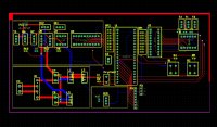
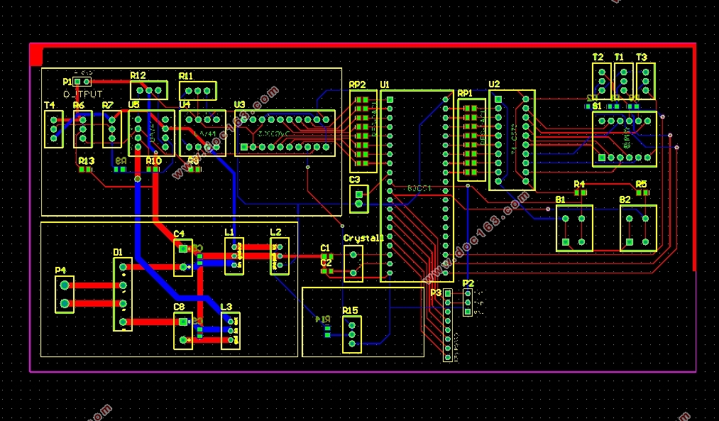
4.1 PCB图的设计 22
4.2 电路焊接及调试 23
4.2.1 焊接 23
4.2.2 调试 24
4.3 电路结果及分析 25
4.3.1 仿真输出电压与理论输出电压关系 25
4.3.2 实际电路测试电压与理论输出的电压关系 26
4.4 本章小结 27 [资料来源:http://Doc163.com]
第5章 总结 28
参考文献 31
附 录 32
致 谢 38
[来源:http://Doc163.com]