
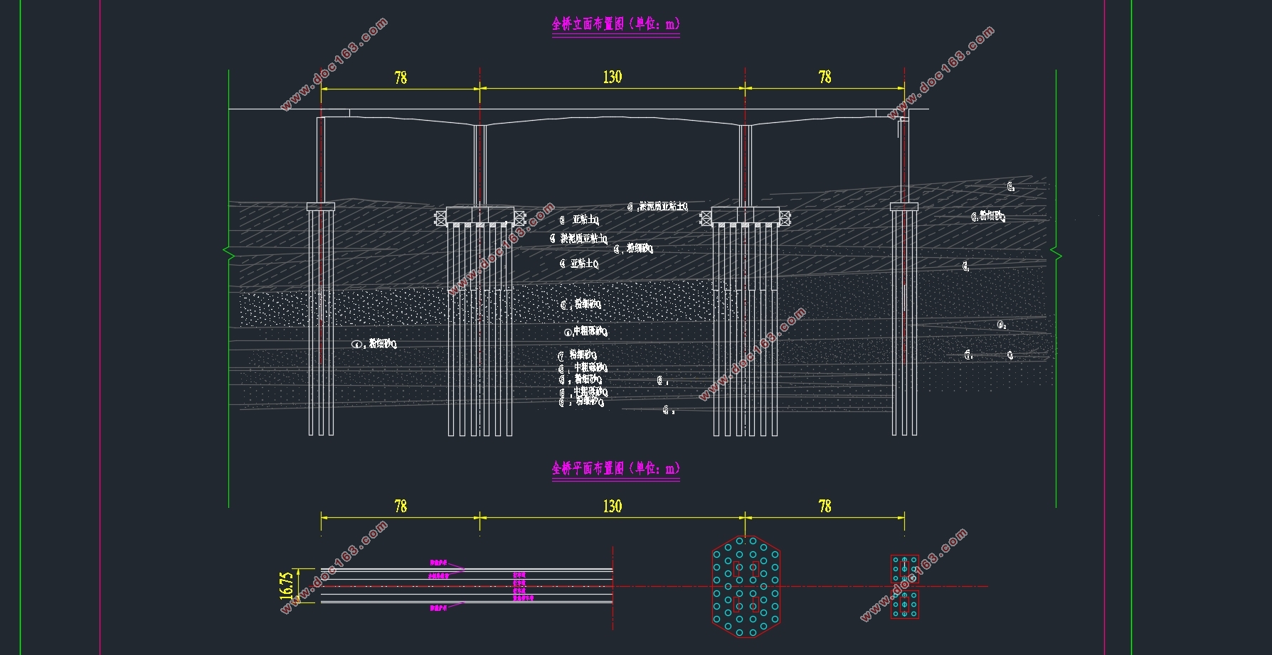
店埠河大桥(78m+130m+78m)上部结构设计与计算分析(含CAD图)
店埠河大桥(78m+130m+78m)上部结构设计与计算分析(含CAD图)(任务书,开题报告,论文计算书20000字,CAD图6张)
摘 要
本次毕业设计为(78m+130m+78m)的 对店埠河大桥的上部结构进行设计与计算。通过采用Midas Civil设计 期间也使用了Excel和Autocad来辅助计算。 施工。
活载内力计算, 算。 行验算。 预应力筋张拉锚固情况图, 进行外文文献的翻译, 明书。
Abstract
The graduation design (78m + 130m + 78m) on the shop bridge River bridge the upperstructure of the design and calculation. Excel and Autocad were also used to assist in the calculation by using Midas Civil design. The main beam adopts the cantilever construction method, the side-span part of the cast-in-place is constructed by the full-stage bracket method, and the cross- After the calculation model is built, the internal force analysis and calculation of the structure are carried out, and then the number of prestressed steel bars is estimated and the reinforcement is arranged. The concrete is designed according to the whole prestressed concrete. And then the dead load, live load calculation, temperature load, bearing uneven settlement, the construction phase of internal force calculation, prestress caused by the internal force calculation. Followed by load combinations and load capacity limit state calculation, while the normal use of the limit state of the stress check. When the bridge model checking design is successful, to draw the bridge cross layout, the main structure of the main beam diagram, the stage of the prestressed steel tension layout, the overall construction sequence diagram. For foreign language translation, and finally the preparation of design calculations and document finishing. [来源:http://Doc163.com]
[资料来源:http://doc163.com]


目 录
第1章 绪论 8
1.1 设计概述 8
1.2 刚构桥的结构受力特点 9
1.2.1 预应力混凝土连续刚构桥的受力特点 9
1.2.2 连续刚构桥与连续梁桥的比较 9
[资料来源:Doc163.com]
1.2.3 刚构桥的优点 9
1.3 刚构桥的施工 10
1.3.1 悬臂浇筑施工 10
1.3.2 施工工艺流程 10
第2章 桥跨布置 12
2.1 桥型布置及孔径划分 12
2.2 截面形式及截面尺寸拟定 12
2.2.1梁高尺寸拟定 12
2.2.2 横截面尺寸拟定 12
2.2.3 桥墩尺寸拟定 13
2.3 单元划分及施工方法 13
2.3.1 单元划分 13
2.4 施工阶段的划分 14
第3章 全桥内力计算 16
3.1 Midas Civil单元划分 16
3.2 设计基本资料 16
3.2.1 材料特性值 16
3.2.2 桥梁技术指标 17
3.2.3 设计依据的规范 17
3.3 边界条件 17
3.4 荷载分布 18
3.4.1 恒载 18
3.4.2活载 19 [资料来源:http://doc163.com]
3.4.3 温度荷载 19
3.4.4 支座沉降 20
3.4.5 收缩徐变 20
3.4.6 施工荷载 20
3.5 恒载内力计算 20
3.6 活载内力计算 27
3.7 支座位移引起的内力 29
3.8 温度荷载引起的内力 29
第4章 预应力钢束设计 31
4.1 荷载组合 31
4.1.1 承载能力极限状态作用效应组合 31
4.1.2 正常使用极限状态作用效应组合 32
4.2 计算原理 33
4.3 预应力钢束估算 35
4.3.1 截面计算 35
4.3.2 预应力钢束估束 38
4.4 纵向预应力钢束的设计与布置 41
4.4.1 预应力钢束的受力特性 41
4.4.2 预应力钢束的布置原则 42
4.4.3 预应力筋布置 42
4.5 横向和竖向预应力钢束布置 44 [来源:http://Doc163.com]
4.5.1 竖向预应力筋 44
4.5.2 横向预应力筋 44
4.6 计算预应力损失及有效预应力 45
4.6.1 预应力筋与预应力管道之间的摩擦引起的预应力损失 45
4.6.2 锚具变形、钢束回缩和接缝压缩引起的应力损失 46
4.6.3 混凝土弹性压缩引起的应力损失 46
4.6.4钢筋松驰引起的应力损失 47
4.6.5 混凝土收缩和徐变引起的预应力损失 47
4.6.6有效应力计算 48
第5章 结构次内力计算 49
5.1收缩徐变次内力 49
5.1.1 收缩徐变理论 49
5.1.2 收缩徐变次内力计算结果 50
5.2 温度次内力计算 51
5.2.1 温度对结构的影响 51
5.2.2 结构温度场 52
5.3 支座不均匀沉降次内力 53
5.4 预应力次内力计算 54
5.4.1 等效荷载原理 55
5.4.2 先期预应力徐变次内力 55
5.4.3 后期合拢预应力弹性次内力 56
第6章 截面验算 58
6.1 内力组合 58
6.2 承载能力极限状态验算 62
6.2.1 正截面抗弯承载力验算 62
6.2.2 斜截面抗剪承载能力验算 63
6.3 抗裂性验算 63
6.3.1 正截面抗裂性验算 63
6.3.2 斜截面抗裂验算 66
6.4 持久状况预应力混凝土构件应力验算 69
6.4.1 混凝土压应力及钢筋拉应力的验算 69
6.5 施工阶段混凝土的应力验算 72
上一篇:44+74+44m公路预应力混凝土连续梁桥滁州大桥上部结构设计(含CAD图)
下一篇:三跨68m+120m+68m西河大桥上部结构设计与计算分析(含CAD图)