
4×30米双向六车道某四跨连续梁桥设计与计算(含CAD图,Midas建模)
4×30米双向六车道某四跨连续梁桥设计与计算(含CAD图,Midas建模)(任务书,开题报告,外文翻译,计算说明书21000字,CAD图8张,Midas建模)
摘 要
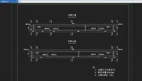
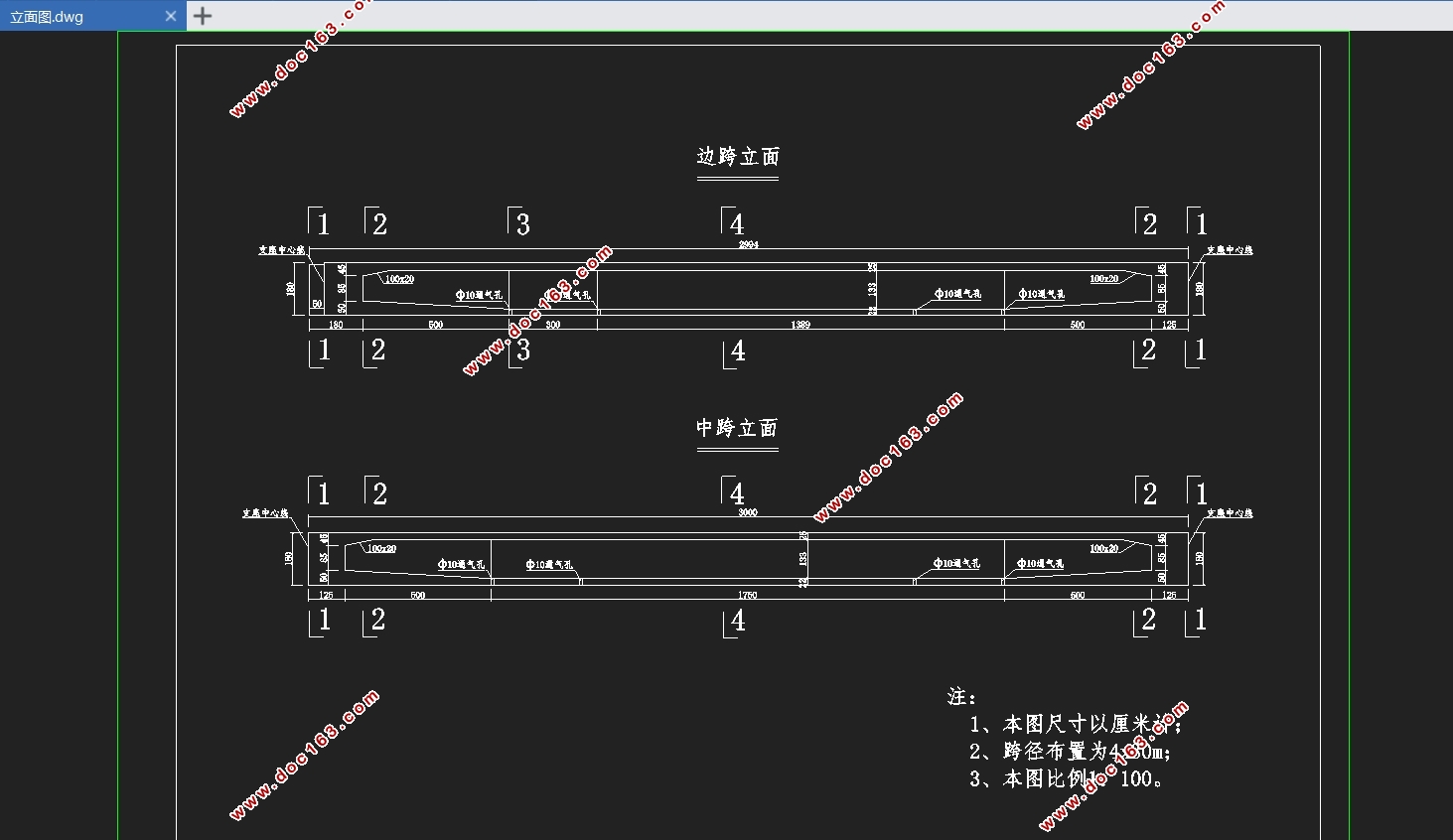
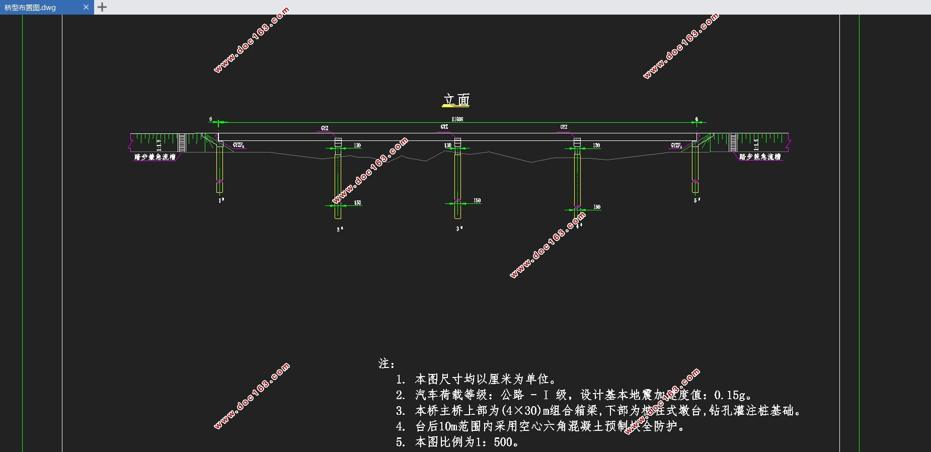
本设计题为“某四跨连续梁桥设计与计算”,分跨为4×30米,双向六车道,横向布置为:0.5m(护栏)+12m(机动车道)+0.5m(中央隔离墩)+12m(机动车道)+0.5m(护栏)=25.5m。设计时首先依据任务书要求和相关规范资料进行桥梁总体布置及结构尺寸拟定,其次使用Midas有限元软件建立模型进行桥梁荷载内力计算及组合,然后估算出预应力钢筋数量并选用布置方法,最后通过Midas有限元软件对主梁截面进行相关验算。同时利用 CAD 软件进行辅助计算,并在验算通过后绘制该桥的主要构造图、预应力束布置图。在计算时,必须要考虑混凝土收缩徐变、温度荷载、支座沉降等因素所引起次内力的影响。
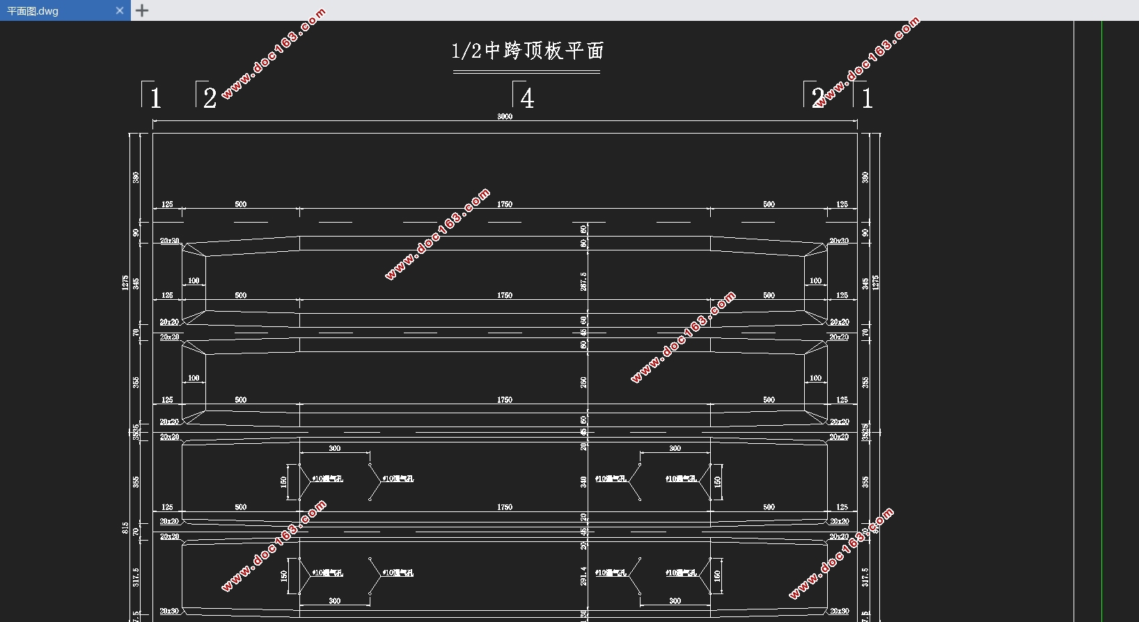
本设计是预应力混凝土连续梁桥的上部结构设计,设计中主要进行了桥梁总体布置及结构尺寸拟定、桥梁荷载内力计算、桥梁预应力钢束的估算与布置、桥梁预内力计算与应力损失和有效应力的验算、次内力的验算、内力组合验算以及主梁截面强度验算等计算与验算分析。同时利用 CAD 软件进辅助计算,并在验算通过后绘制预应力混凝土连续梁结构设计的主要构造图、预应力束布置图及施工顺序图。
[来源:http://Doc163.com]
关键词:预应力连续梁桥 Midas(civil)有限元软件 建模 结构分析
Design and calculation of a four-span continuous beam bridge
Abstract
The design title is “Design and calculation of a four-span continuous beam bridge” with a span of 4×30 meters and two-way six lanes. The horizontal layout is: 0.5m (guard rail) +12m (motor vehicle lane) +0.5m (central isolation pier) ) +12m (motor vehicle lane) + 0.5m (guard rail) = 25.5m. In the design, the overall layout and structural dimension of the bridge are firstly determined according to the requirements of the task book and relevant normative data. Secondly, the model is used to calculate and combine the internal forces of the bridge load using Midas finite element software, and then the number of prestressed steel bars is estimated and the arrangement method is selected. Midas finite element software performs related checking on the main beam section. At the same time, the CAD software is used for auxiliary calculation, and the main structural diagram, prestressed beam layout diagramof the bridge are drawn after the verification is passed. In the calculation, the influence of secondary internal force caused by factors such as concrete shrinkage and creep, temperature load, and bearing settlement must be considered. [资料来源:http://www.doc163.com]
This design is the upper structure design of prestressed concrete continuous girder bridge. The design of the overall layout and structure of the bridge, the calculation of the internal force of the bridge load, the estimation and arrangement of the prestressed steel beam of the bridge, the calculation of the pre-internal force of the bridge and the stress loss are mainly carried out. Calculation and verification analysis of effective stress, calculation of secondary internal force, internal force combination check, and main beam section strength check. At the same time, the CAD software is used to assist the calculation, and the main structural drawing, prestressed beam layout and construction sequence diagram of the prestressed concrete continuous beam structure design are drawn after the verification.
Keywords: prestressed continuous beam bridge; Midas (civil) finite element software; modeling; structural analysi
2.1 工程概况
本次毕业设计为某公路桥,采用全预应力混凝土连续梁结构,拟定分跨为4×30米,双向六车道,横向布置为:0.5m(护栏)+12m(机动车道)+0.5m(中央隔离墩)+12m(机动车道)+0.5m(护栏)=25.5m。荷载等级:公路-I级,不设人行道,无人群荷载。设计采用有限元软件 Midas 进行相关设计计算。本次设计施工方法采用满堂支架现浇施工,这种施工方法是最为原始和基本。由于连续梁的内力与其施工方法密切相关,故采用该方法可使内力计算清晰简洁。
[资料来源:https://www.doc163.com]
2.2 设计基本资料
2.2.1 主要技术标准
汽车荷载等级:公路-I级;
2.2.2 主要材料
(1)混凝土
表 2-1 混凝土表格
强度等级 弹性模量(MPa) 容重(kN/m³) 线膨胀系数 fck(MPa) ftk(MPa) fcd(MPa) ftd(MPa)
C50 34500.00 25.00 1.000e-005 32.40 2.65 22.40 1.83
(2)预应力钢筋
表 2-2 预应力材料表格
预应力钢筋 弹性模量(MPa) 容重(kN/m³) 线膨胀系数 fpk(MPa) fpd(MPa) fpd(MPa)
Strand1860 195000.00 78.50 1.200e-005 1860.0 1260.00 390.00
[来源:http://www.doc163.com]


目 录
第一章 绪论 1
第二章 设计准备 2
2.1 工程概况 2
2.2 设计基本资料 2
2.2.1 主要技术标准 2
2.2.2 主要材料 2
2.2.3 设计荷载 3
2.2.4 桥面铺装 3
2.2.5 温度作用 3
2.2.6 支座沉降 3
2.2.7 施工方法 4
2.2.8 设计规范 4
第三章 结构设计 5
3.1 桥型布置及孔径划分 5
3.2截面形式及截面尺寸拟定 5
3.2.1截面形式 5
3.2.2梁高拟定 6
3.2.3细部尺寸 6
3.2.4横截面构造图 7
第四章 结构有限元建模 9
4.1 定义材料、截面 9
4.1.1定义材料 9
4.1.2定义截面 10
4.2建立节点、单元 10
4.3边界条件 11
4.4支座沉降 12
4.5添加荷载 12
4.5.1定义静力荷载工况 12
4.5.2恒载输入 13
4.5.3移动荷载 13
4.5.4 温度荷载 15
4.5.5 荷载组合说明 16
4.6 施工过程 17
第五章 主梁内力计算结果 19
5.1 永久作用计算 19 [版权所有:http://DOC163.com]
5.1.1 自重 19
5.1.2 二期恒载 23
5.2 可变作用计算 27
5.2.1 移动荷载 27
5.3 次内力计算 32
5.3.1 温度荷载 32
5.3.2支座沉降内力 36
5.4作用效应组合 37
5.4.1 基本组合 37
5.4.2 频遇组合 41
5.4.3 准永久组合 45
第六章 预应力钢筋计算 50
6.1预应力钢筋的估算 50
6.2 预应力钢筋布置 52
6.2.1预应力钢筋布置原则 52
6.2.2钢束特性值 53
6.2.3横断面布置 53
6.2.4立面及平面布置 53
6.3预应力损失计算 54
6.3.1控制应力 54
6.3.2各项预应力损失及计算原则 55
6.3.3 有效预应力 55
6.3.4 钢束预应力损失 55
第七章 主梁截面验算 57
7.1施工阶段法向压应力验算 57
7.1.1 计算依据 57
7.1.2 验算结果 57
7.2 受拉区钢筋的拉应力验算 59
7.2.1 计算依据 59
7.2.2 计算结果 60
7.3使用阶段正截面抗裂验算 61
7.3.1 计算依据 61
7.3.2 验算结果 62
7.4使用阶段斜截面抗裂验算 62
7.4.1计算依据 62
7.4.2计算结果 63
7.5使用阶段正截面压应力验算 63
7.5.1 计算依据 63
7.5.2 验算结果 64
7.6使用阶段斜截面主压应力验算 64
7.6.1 计算依据 64
7.6.2 验算结果 65
7.7使用阶段正截面抗弯验算 65
7.7.1 计算依据 65
7.7.2 验算结果 66
7.8使用阶段斜截面抗剪验算 67
7.8.1 计算依据 67
7.8.2 验算结果 69
参考文献 71
致谢 72
附录 73
附表1 特征截面施工阶段法向压应力验算数据表 73
附表2 特征截面使用阶段正截面抗裂验算表格 83
附表3 特征截面使用阶段斜截面抗裂验算表格 88
附表4 使用阶段正截面压应力验算表格 93
附表5 使用阶段斜截面主压应力验算表格 98
附表6 使用阶段正截面抗弯表格 103
附表7 使用阶段正截面抗弯表格 109 [资料来源:http://doc163.com]
上一篇:某连续梁桥第三联设计与计算(二跨40=40m)(含CAD图)
下一篇:典型高铁桥梁(32m简支梁)技术状态检测及分析(含CAD图)