
76+150+76m连续刚构桥偏岩嘴大桥设计(含CAD图)
76+150+76m连续刚构桥偏岩嘴大桥设计(含CAD图)(任务书,开题报告,论文计算书18000字,CAD图纸3张,midas模型)
摘 要
本设计主要借助Midas和CAD软件根据当地地形环境设计了一座跨谷大桥,起初设计了三个方案,分别是连续刚构桥、双塔双索面斜拉桥和上承式拱桥,最后通过桥梁方案比选认为连续刚构桥是最佳方案。本设计方案为76+150+76m连续刚构桥,两端分别连接了2*20m的简支梁来进行过渡。本桥施工方法为悬臂灌注施工。
本文主要对于主梁部分进行了详细的设计和验算,简支梁部分没具体设计分析。
在设计梁时,本文先根据连续刚构桥的相关规范对其支点截面和跨中截面和桥墩截面在cad图中进行了设计,本桥宽12.5m,由于桥为上下行分离式,所以整个过程本文以某一方向的桥为主进行了设计。并根据地形和连续刚构桥边跨主跨比的相关规范将桥设计成76+150+76m的桥跨,两端分别用2*20m的简支梁连接到引桥。并在cad图中对桥进行分块。接下来将各节点输入到midas中,并建立单元,再将截面形状输入进去,并将跨中截面和支点截面之间设为二次抛物线变化的变截面组,然后设置好边界条件,这样大致桥型已经完成。接下来设置各种材料并分配,将事先在cad中设计好的预应力筋输入到midas并进行张拉。然后设置各种荷载工况。在这个过程中本设计设置了自重、预应力荷载、防撞墙荷载、桥面铺装和挂篮荷载等静力荷载,移动荷载中只设置了车道荷载。接下来对边界、结构和荷载进行分组。然后开始建立施工过程。最后运行无误之后提取结果并生成计算书。
关键词:连续刚构桥;midas;悬臂浇筑施工。
Abstract
This design mainly by Midas and CAD software according to the local terrain environment designed a cross Valley bridge. At first, three schemes are designed, which are the continuous rigid frame bridge, the cable-stayed bridge and the upper deck arch bridge, and finally the continuous rigid frame bridge is selected by the comparison. This design scheme is 76+150+76m continuous rigid frame bridge, whose two ends are connected with the 2*20m simply supported beam to carry on the transition. The construction method of this bridge is cantilever construction.
This paper focuses on the main beam part of the detailed design and checking, charpy section did not specifically design analysis.
In designing the beam, the paper first designed its fulcrum section and the middle section and piers in CAD sectional view of a continuous steel bridge relevant norms.This bridge width 12.5m, because the bridge is up and down the separation type, so the whole process in this paper, based on a certain direction of the bridge design.And in accordance with the relevant norms terrain and continuous rigid frame bridge across the main bridge span ratio will be designed to 76 + 150 + 76m span bridge, both ends with 2 * 20m simply supported beam is connected to the bridge.And the bridge was partitioned in CAD. Next to each node input into the Midas, and establish the unit, then cross section shape is entered,and cross section and fulcrum section is arranged between the second parabolic curve of variable cross-section of the group, and then set the boundary conditions, which would roughly bridge has been completed.Then, set a variety of materials and assigned to each unit. Input the prestressing tendon to the Midas and the tension is carried out.And then set up a variety of load conditions. In this process, this paper sets up the static load such as the self weight, the pre-stressed load, the load of the anti collision wall, the deck pavement and the load of the hanging basket. Only lane load is set in moving load. Next, the boundary, structure, and load are grouped. And then began to build the construction process.Finally, the results can be extracted after running correctly, and then generate calculations.
[来源:http://www.doc163.com]
Keywords: Prestressed concrete; continuous rigid frame bridge; cantilever casting
2.1 工程概况
1. 本桥位于湖北西部沪蓉国道主干线宜昌至恩施高速公路上,道路设计等级为山区高速公路。设计水位为110m,枯水位为102m,线路在桥址范围内为直线,两边的引道标高均为225m。桥中线与河槽方向正交。
2. 地质情况如下:
全断面为1m左右的覆盖层,其下为2~3m的强风化灰岩和弱风化灰岩。
3. 温度变化:均匀升温23℃,均匀降温23℃。
4. 设计风速27.6m/s。
5. 材料:分析自定
6. 桥址处纵断面的数据见下表。(单位:m)
[来源:http://www.doc163.com]


[版权所有:http://DOC163.com]


目录
第一章、绪论 1
第二章、基本信息与方案比选 3
2.1 工程概况 3
2.2 技术标准 3
2.3 方案比选 4
2.4 结构概述 8
2.5 主要材料及材料性能 10
2.6 计算原则、内容及控制标准 10
第三章、模型建立与分析 11
3.1 计算模型 11
3.1.1分段原则 11
3.1.2 具体分段 11
[资料来源:https://www.doc163.com]
3.1.3 施工方法简介 12
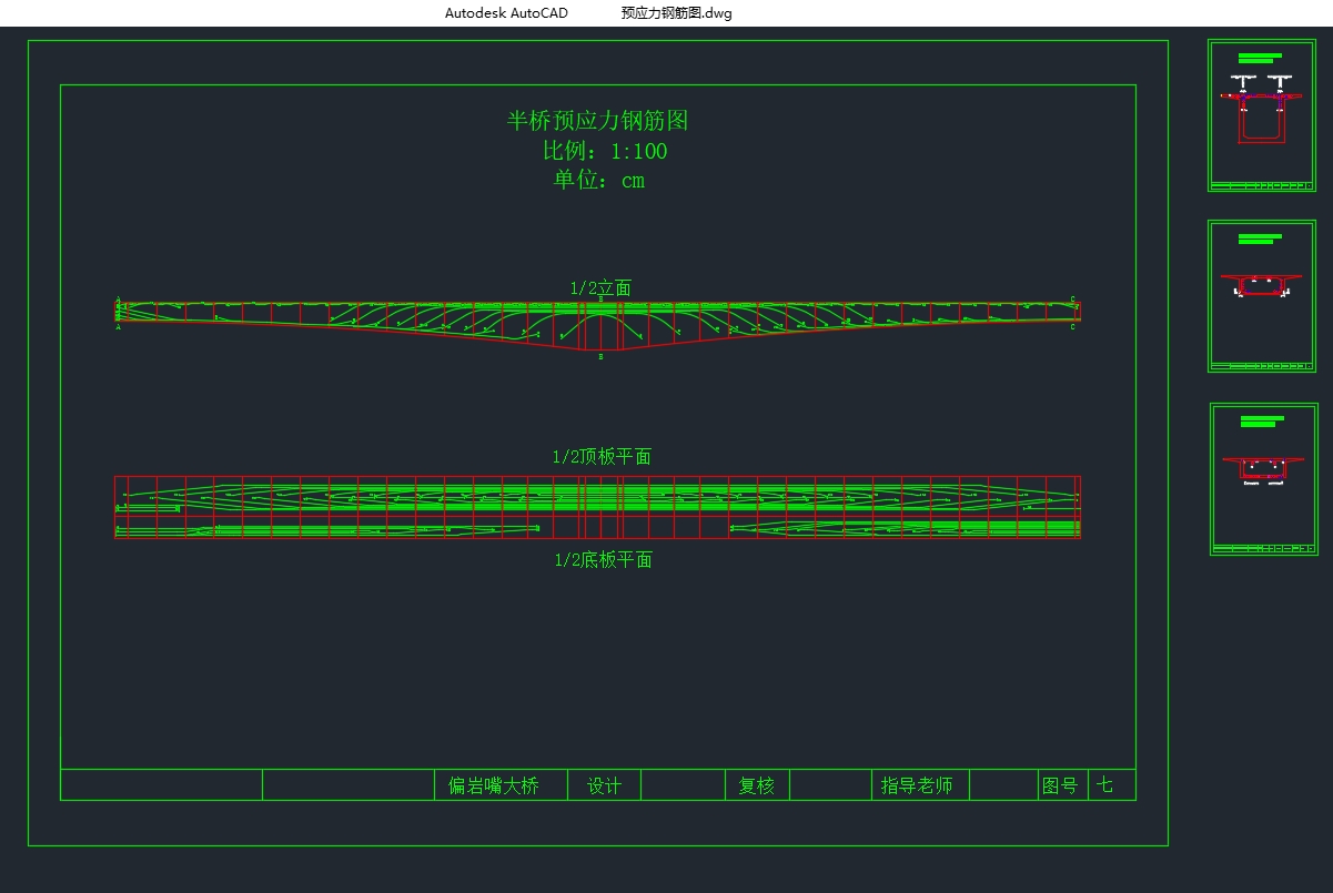
3.2 主要钢筋布置图 13
3.3 截面特性及有效宽度 14
3.4 荷载工况及荷载组合 15
第四章、荷载内力计算 17
4.1 恒载内力计算 17
4.2 活载内力计算 21
4.3 内力组合 27
第五章、承载能力极限状态验算 33
5.1 截面受压区高度 33
5.2 承载能力极限状态基本组合 33
5.3 正截面抗弯承载能力验算 33
5.3.1 正截面抗弯承载能力极限状态验算理论 33
5.3.2 正截面正常使用极限状态应力验算理论 35
5.4 支反力计算 46
第六章、构件应力验算结果 47
6.1 正截面混凝土法向压应力验算 47
6.2 正截面受拉区钢筋拉应力验算 53
上一篇:预应力混凝土连续梁桥(40+70+40)m施工控制(含CAD图,Midas)
下一篇:某匝道曲线桥(3×28)m等截面预应力混凝土连续梁桥设计(含CAD图)