
单缸气动楔式弹性闸板闸阀设计(含CAD零件图装配图)
单缸气动楔式弹性闸板闸阀设计(含CAD零件图装配图)(任务书,开题报告,外文翻译,论文说明书14900字,CAD图7张)
摘 要
阀门是在流体系统中,用来控制流体的方向、压力、流量的装置是使配管和设备内的介质(液体、气体、粉末)流动或停止并能控制其流量的装置。
阀门是管路流体输送系统中控制部件,它是用来改变通路断面和介质流动方向,具有导流、截止、节流、止回、分流或溢流卸压等功能。用于流体控制的阀门,从最简单的截止阀到极为复杂的自控系统中所用的各种阀门,其品种和规格繁多, 阀门的公称通径从极微小的仪表阀大至通径达10m的工业管路用阀。可用于控制水、蒸汽、油品、气体、泥浆、各种腐蚀性介质、 液态金属和放射性流体等各种类型流体地流动 ,阀门的工作压力可从0.0013MPa到1000MPa 的超高压,工作温度从-270℃的超低温到1430℃的高温。
阀门的控制可采用多种传动方式, 如手动、电动、液动、气动、涡轮、电磁动、电磁液动、电液动、气液动、正齿轮、伞齿轮驱动等;可以在压力、温度或其它形式传感信号的作用下, 按预定的要求动作,或者不依赖传感信号而进行简单的开启或关闭,阀门依靠驱动或自动机构使启闭件作升降、滑移、旋摆或回转运动, 从而改变其流道面积的大小以实现其控制功能。
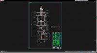
本设计是以楔式弹性闸板闸阀为设计对象,主要介绍了闸阀的结构和手动-气动转换装置的特点,以及工作原理。阀门设计包括很多内容,包括通用部件的设计和专用部件的设计,又包括强度、尺寸等计算过程。其中,设计阀门的关键是阀门的密封设计,其中阀杆的强度及稳定性计算也是重点。
阀门设计整个过程包括这样几个步骤。按设计参数确定结构,进行方案确定,工作原理,进行受力分析,强度的计算,稳定性的校核,材料选择,测绘总装备图和手动机构装配图和气缸及阀门的全部零件图(Auto CAD)。对闸板密封面进行受力分析,阀门强度计算以及闸杆稳定性校核是重难点。其中重点步骤如下。首先对工作的环境进行确定,选择合适方案,对所设计的零件进行受力分析;然后根据国家标准和推荐的尺寸来确定实际的尺寸;最后进行强度校核,绘制闸阀工程图。
关键词:楔式闸阀 气动 密封面 弹性闸板
Abstract
The valve is in a fluid system for controlling the direction of the fluid, the pressure device, is to make the flow pipe and the medium inside the device (liquid, gas, powder) or stopped flow apparatus and its flow control.
Pipeline valves are controlled fluid delivery system components, which is used to change the channel section and flow direction of medium, with diversion, off, throttling, non-return, diversion or overflow relief functions. For fluid control valves, valves off from the most simple to the most complex automatic control valve used in the system, and its many varieties and specifications, the valve nominal diameter from large to tiny instrument valve diameter up to 10m industrial pipeline valves. EHV can be used to control the water, steam, oil, gas, mud, corrosive media, liquid metals and radioactive fluids and other types of fluid flow, the valve working pressure from 0.0013MPa to 1000MPa, the working temperature from 1430 ℃ ultra-low temperature to a high temperature of -270 ℃ .
Control valve can be a variety of drive, such as manual, electric, hydraulic, pneumatic, turbine, electromagnetic move, electromagnetic hydraulic, electro hydraulic, pneumatic and hydraulic, spur gears, bevel gear drive and the like; in pressure, temperature or the role of other forms of sensor signals, according to the requirements prescribed action, or do not rely on the sensor signal and a simple on or off, the valve is being driven or automatic mechanism to open and close member for lifting, sliding, rotating or rotary pendulum movement, thus changing the size of its flow area to achieve its control function.
This design is a wedge type elastic single gate valve for the design object, the main introduction of the valve structure and manual pneumatic conversion device characteristics, and its working principle. Valve design includes a lot of content, including common components design and special parts design, and including strength, size and so many calculation process. Among them, the key valve design valve seal design, which valve stem strength, as well as the calculation of the stability is the focus.
Valve design throughout the process consists of several steps. According to the design parameters determine the structure, project demonstration and working principle stress analysis, strength calculation, stability check, material selection, surveying and mapping equipment figure and mechanism of manual assembly drawing and the cylinder and valve all the parts diagram with Auto CAD drawing. The stress analysis of the sealing surface, the stability of the brake rod and the strength of the valve are the most difficult points.. Including such a few key steps. First on the working environment are determined, choose the appropriate scheme, to design the parts stress analysis; then according to the national standard and recommended dimensions to determine the actual size; finally, the strength check, drawing valve engineering drawing. [资料来源:https://www.doc163.com]
Keywords: the hand pneumatic change; seal; dyadic valve of wedge; elasticity brake board

[资料来源:http://doc163.com]
目 录
摘要 I
Abstract II
第一章 绪论 1
1.1选题的意义 1
1.2闸阀的定义 1
1.3闸阀的种类 2
1.4 国内外阀门的发展 2
1.4.1 国外的阀门发展 2
1.4.2国内阀门的发展 3
第二章 气动—手动楔式闸板闸阀的工作原理及其结构特点 5
2.1 工作原理 5
2.2 结构设计特点 5
2.3气动阀的维护注意事项 6
第三章 阀门的设计与计算 8
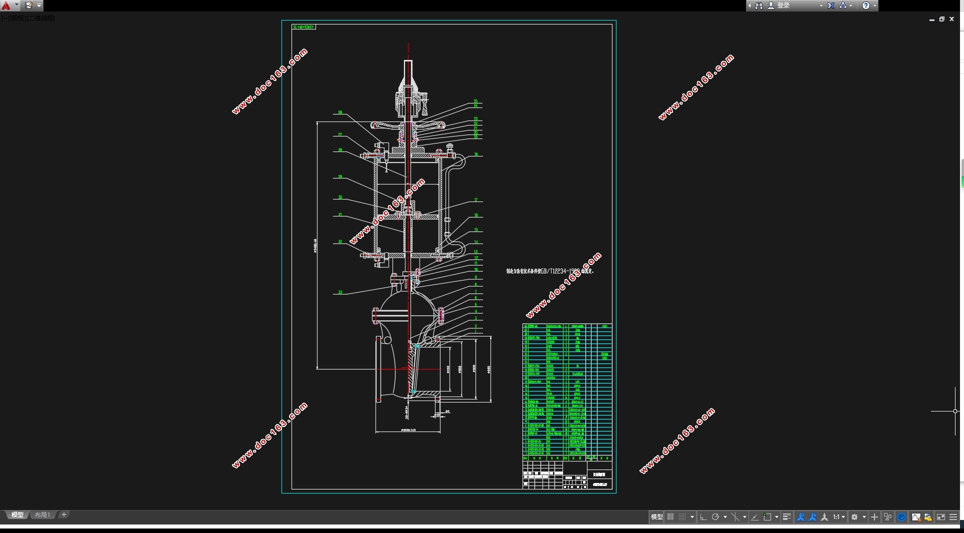
3.1 阀体的设计与计算 8
3.1.1 阀体的功能 8
3.1.2 阀体的选材 8
3.1.3 阀体的结构形式和制造方法 9
3.1.4确定阀体结构长度和连接尺寸 9
3.1.5 阀体壁厚的设计与计算 10
3.1.6 中法兰的设计与计算 11
3.1.7密封面的设计与计算 15 [资料来源:http://www.doc163.com]
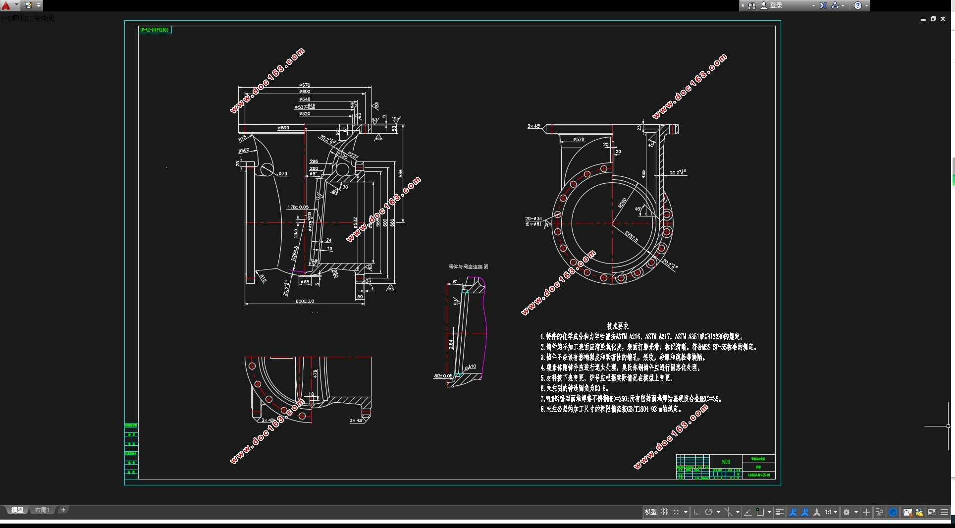
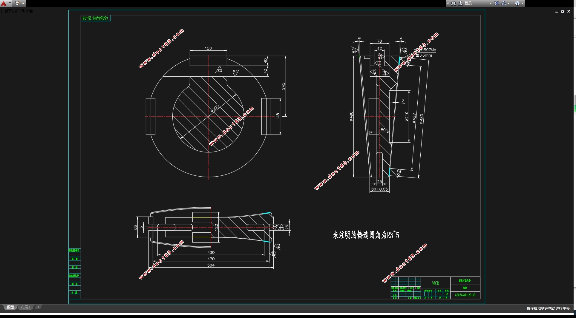
3.2闸板的设计与计算 17
3.2.1闸板密封面的内径与宽度的选取 17
3.2.2弹性闸板结构设计与计算 17
3.2.3闸板的厚度校核 18
3.3阀杆的设计与计算 19
3.3.1闸阀阀杆的总轴向力 19
3.3.2阀杆的直径估算 20
3.3.3阀杆的强度校核 20
3.3.4阀杆的稳定性校核 22
3.3.5阀杆主要尺寸的确定 23
3.4阀盖及填料装置的设计与计算 24
3.4.1阀盖的设计与计算 24
3.4.2 填料压盖的设计与计算 25
3.4.3 上密封座尺寸 30
3.5气缸的设计与计算 31
3.5.1气缸的直径粗估算与选取 31
3.5.2 气缸的校核 31
3.6 其他主要零件的设计与校核 32
3.6.1 滚动轴承的选取 32
3.6.2 手轮直径的确定 33
[版权所有:http://DOC163.com]
3.6.3 阀杆螺母的校核 33
第四章 结论与展望 35
4.1结论 35
4.2展望 36
参考文献 37
致谢 38 [来源:http://Doc163.com]
上一篇:GQ300t40m桅杆式起重机总体与起升机构设计(含CAD零件装配图)