
轨道打磨机构设计(含CAD图)
轨道打磨机构设计(含CAD图)(外文翻译,论文说明书17000字,CAD图4张)
摘 要
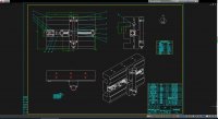
本文根据国内外现有轨道打磨机技术和企业实际需求设计出一种不同于传统轨道打磨机构的创新性轨道打磨机构,该机构的设计灵感来自于装备制造业中的数控铣床,把铣床的工作原理运用到轨道打磨上来,改善原有产品在环保性和经济性。由于本次毕业设计的时间有限,根据企业指导技术人员的建议,我主要进行轨道打磨机构的进给机构的设计与三维建模,轨道打磨机构的打磨刀头部分设定为已知。
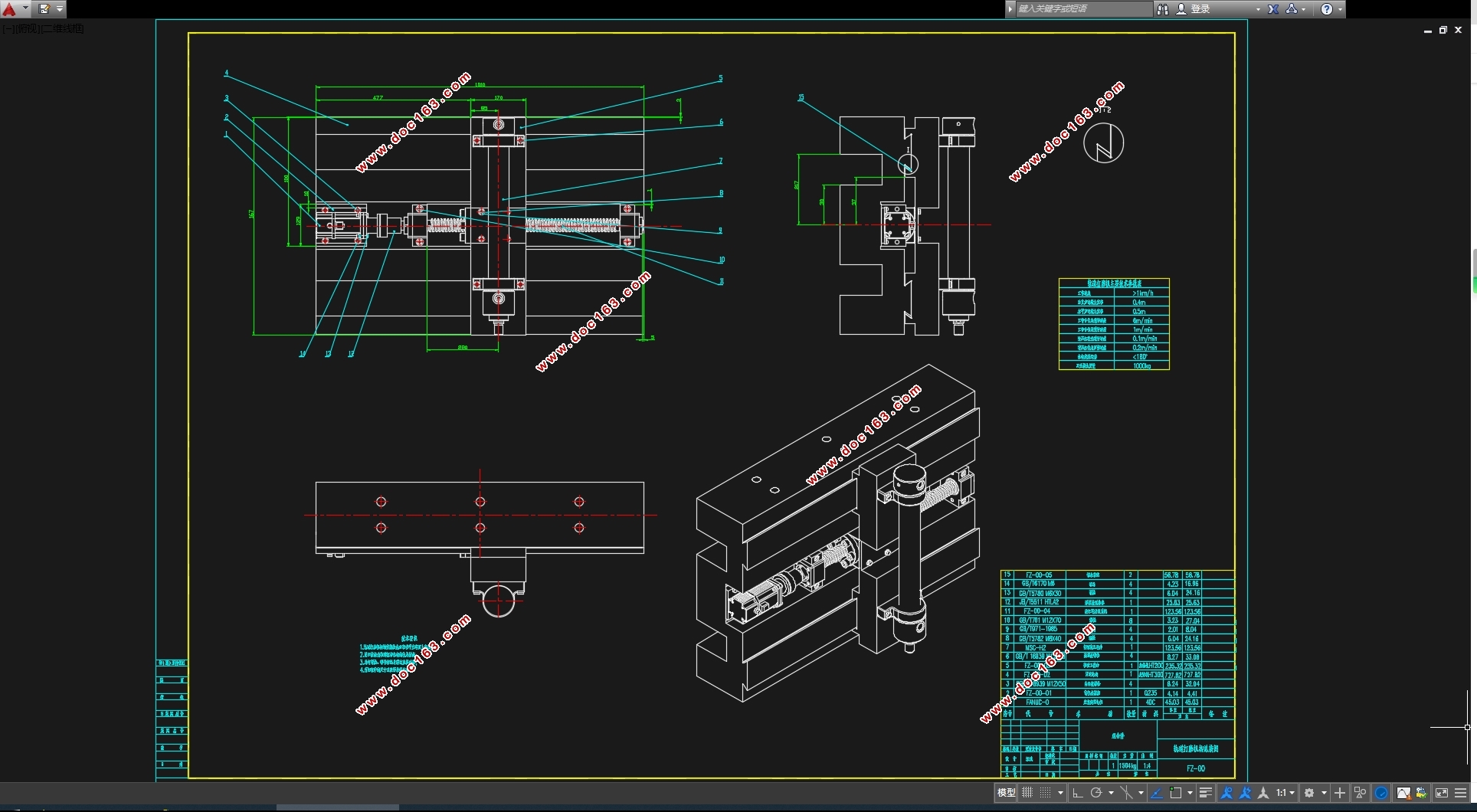
本次设计的创新点在于把传统的磨头式打磨改变为铣刀铣磨与磨头打磨相结合的方式,进给机构由传统的液压驱动变为电机与液压分别驱动。结构部分借用机床工作台的设计原理,在保证打磨机构的结构强度,刚度,稳定性和运行精度的前提下,尽可能的减轻结构自重。轨道打磨机构的结构设计参照有关设计手册和已有产品设计说明书。
关键词:三维建模 传动计算 结构校验
Abstract
According to the existing rail grinding machine technology and the actual needs of enterprises at home and abroad, this paper designs an innovative rail grinding mechanism which is different from the traditional rail grinding mechanism. the design inspiration of this mechanism comes from the CNC milling machine in the equipment manufacturing industry. the working principle of the milling machine is applied to the rail grinding to improve the environmental protection and economy of the original products. Because the graduation design time is limited, according to the enterprise guide technical personnel's suggestion, I mainly to track grinding mechanism of feed mechanism design and three-dimensional modeling, track grinding mechanism of grinding head part set to known.
The innovation of this design is to change the traditional grinding head type grinding into the way of combining milling cutter grinding and grinding head grinding. the feed mechanism is changed from the traditional hydraulic drive to the motor and hydraulic drive respectively. The structure part borrows the design principle of the machine tool worktable, and lightens the self-weight of the structure as much as possible on the premise of ensuring the structural strength, rigidity, stability and operation precision of the grinding mechanism. The structural design of the track grinding mechanism shall refer to the relevant design manual and the existing product design manual.
Key words: three - dimensional modeling Transmission calculation structural check
本次课题的设计对象为一种新型轨道打磨机构的进给机构,其基本参数如下:
表2.1 技术参数
技术参数 数值
工作速度 >1km/h
垂直方向最大位移 0.4m
水平方向最大位移 0.5m
工作台快速进给速度 6m/min
工作台铣削进给速度 1 m/min
刀头模块垂直进给速度 0.1 m/min
刀头模块快速回程速度 0.2 m/min
机构旋转运动 ≤180°
刀头模块质量 1000kg
[资料来源:www.doc163.com]
目录
摘要 I
Abstract II
第1章绪论 1
1.1 课题研究背景 1
[资料来源:www.doc163.com]
1.2 国内外研究现状 1
1.3 课题研究内容 2
1.3.1 设计目的、主要功能以及技术要求 2
1.3.2 设计的主要流程 2
第2章总体设计 4
2.1 基本技术参数 4
2.2 结构总体力学分析 4
2.2.1 轨道打磨机构总体设计图 4
2.2.2 轨道打磨机构ANSYS静定分析 5
2.3 铣削阻力计算 6
第3章水平运动导轨副设计 7
3.1 移动工作台导轨设计 7
3.1.1 工作台受力分析: 7
3.1.2 导轨的选型及校核 8
3.2 导轨间隙调整装置 10
3.2.1 导轨间隙调整装置的一般要求 10
3.2.2 镶条结构及界面尺寸的选取 11
3.3 导轨副的材料及其热处理 11
3.3.1 导轨副材料的选择 11
3.3.2 导轨的热处理 11
3.4 本章小结 12 [资料来源:https://www.doc163.com]
第4章滚珠丝杠运动副设计 13
4.1 滚珠丝杠运动副传动特点 13
4.2 滚珠丝杠运动副计算选型 13
4.2.1 丝杠传动计算的已知参数 13
4.2.2 滚珠丝杠运动副的结构计算 14
4.2.3 滚珠丝杠支撑组合单元的设计选型 16
4.2.4 润滑、密封和防护 17
4.3 本章小结 17
第5章伺服电机的计算选型 19
5.1 直流伺服电机的性能特点 19
5.2 直流伺服电机选型 19
5.2.1 电机外负载的转动惯量的计算 20
5.2.2 伺服电机电机轴上等效负载转矩的计算 20
5.2.3 伺服电机规格型号 21
5.2.4 直流伺服电机电磁制动 21
5.3 联轴器及键的设计选型 21
5.3.1 联轴器的选型 21
5.3.2 连接键的选取 22
5.4 本章小结 22
第6章液压伺服系统的设计选型 23
[资料来源:http://Doc163.com]
6.1 液压伺服油缸的性能特点 23
6.2 液压油缸的设计选型 23
6.2.1 液压缸类型的选择 23
6.2.2 液压缸主要结构参数计算 24
6.2.3 液压缸型号的选择 25
6.3 本章小结 27
第7章经济性与环保性分析 28
7.1 轨道打磨机构的经济性分析 28
7.2 轨道打磨机构环保性分析 29
第8章总结与展望 30
8.1全文总结 30
8.2 未来展望 30
参考文献 32
致谢 33 [资料来源:www.doc163.com]
上一篇:简易升降机械手设计及三维建模(含CAD图,SolidWorks三维图)