
口服液灌装及封盖机构设计(含CAD零件装配图,SolidWorks三维图)
口服液灌装及封盖机构设计(含CAD零件装配图,SolidWorks三维图)(论文说明书13000字,CAD图7张,SolidWorks三维图)
摘要
经过这些年的发展,我国的科学技术水平越来越高,更多的工厂都开始了机械化和无人化的改造。机械化和无人化可以极大的提高工厂的生产效率,也可以降低人工工资成本,可以说是一举多得的产业升级之路。
本文主要设计的是一款口服液的灌装与拧盖设备,口服液现在在医药行业和保健品行业的使用率越来越高,对于口服液的生产现在也有了成熟的生产线和自动化机械。对于我国人口众多的国情来说,现在需要的不是大型化的模块化机械设备,而是造价较为低廉,结构简单容易维修的小型化整合设备。这种设备比较适合我国的家庭式作坊的生产模式。
现在市场上的灌装机与封盖机大多是人工与机械合作的配套性生产设备。机械生产过程中还需要人工的参与与控制。可以说是将机械设备的生产效率降低以用来配合人工生产。
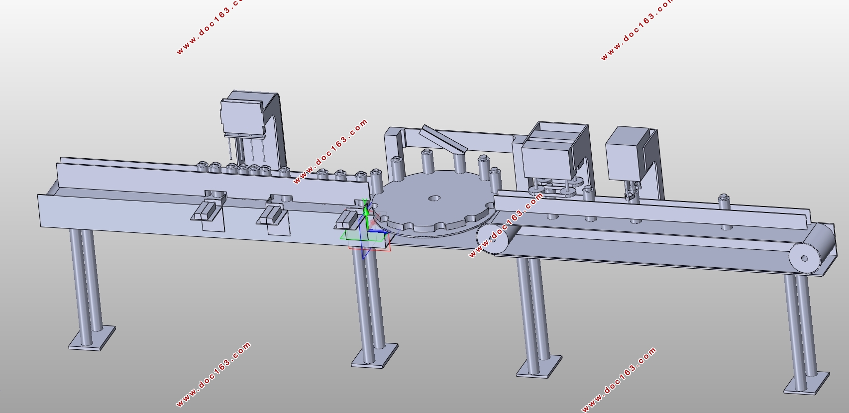
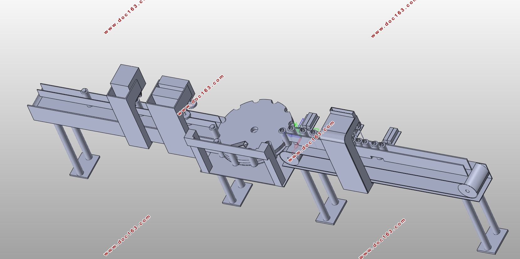
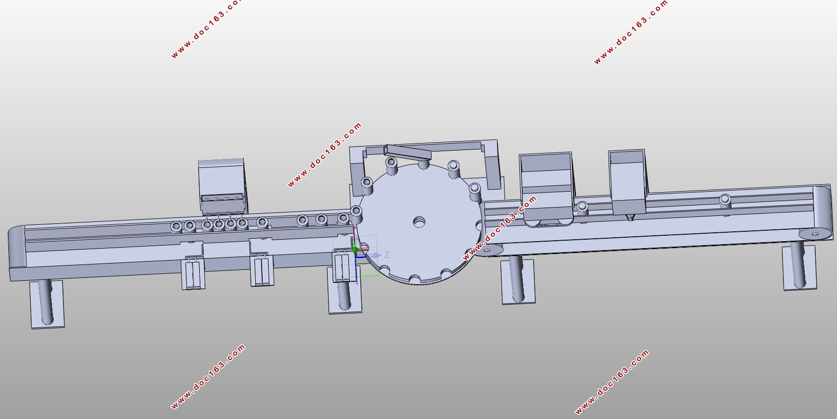
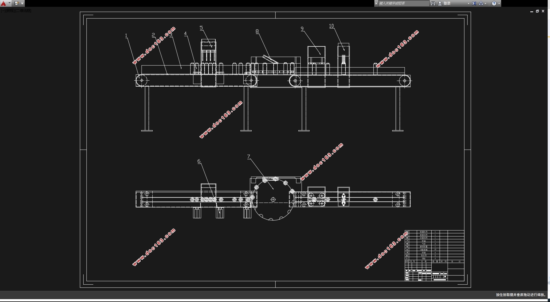
本文的主要内容是设计一款自动化的口服液灌装与拧盖设备。本文主要对灌装设备与拧盖设备的机械结构进行设计,包括口服液瓶的运动机构,灌装机构的选取,放盖机构的选取,拧盖机构的选择等等。还有主要零部件的计算与校核,主要零部件的二维图纸的绘制,还有整个设备的三维数模的建立。 [资料来源:Doc163.com]
本文的主要目的是为了了解设备在国内行业的发展程度,同时也是为了强化本科学习的知识和实际的动手能力,为了进入社会进行的一系列的铺垫与锻炼。
关键词:灌装机构;拧盖机构;传送;自动化
ABSTRACT
After these years of development, China's scientific and technological level has become higher and higher, and more factories have begun to undergo mechanized and unmanned transformation. Mechanization and unmanned production can greatly improve the production efficiency of factories, and can also reduce labor wage costs. It can be said that it is a road to industrial upgrading that can achieve more with one stroke.
The main design of this article is a filling and capping device for oral liquid. Oral liquid is now increasingly used in the pharmaceutical and health care industries, and there are mature production lines and automated machinery for the production of oral liquid. For the national situation of China with a large population, what is needed now is not large-scale modular mechanical equipment, but small-scale integrated equipment with relatively low cost and simple structure and easy maintenance. This equipment is more suitable for the production mode of domestic workshops in China.
Currently, the filling and capping machines on the market are mostly matching production equipment that cooperate manually and mechanically. The mechanical production process also requires manual participation and control. It can be said that the production efficiency of mechanical equipment is reduced to match manual production.
The main content of this article is to design an automated oral liquid filling and capping device. This article mainly designs the mechanical structure of the filling and capping equipment, including the movement mechanism of the oral liquid bottle, the selection of the filling mechanism, the selection of the capping mechanism, the selection of the capping mechanism, and the selection of the capping mechanism. There is also the calculation and verification of main components, the drawing of two-dimensional drawings of main components, and the establishment of three-dimensional mathematical models of the entire equipment.
The main purpose of this article is to understand the development level of equipment in the domestic industry, and also to strengthen the knowledge and practical skills learned by undergraduate students, as well as a series of preparations and exercises for entering the society. [版权所有:http://DOC163.com]
Key words: filling mechanism; Screwing mechanism; delivery; automation
主要参数:
生产率:不低于100瓶/分钟;
同步生产数量:可进行4灌装头同时灌装;
口服液尺寸:口服液瓶高107mm,外径35mm。
1.3.2 设计要求:
(1)达到卫生部的关于食品\药品卫生要求;
(2)传动部分要置于机体内;
(3)电源电压:380V/50Hz;
(4)要实现灌装、放盖、压内盖和旋外盖;
[资料来源:https://www.doc163.com]
 [资料来源:http://doc163.com]
目录
摘要 I
ABSTRACT II
1 绪论 3
1.1 本课题的研究内容和意义 3
1.2 国内外的发展概况 3
1.3 预期达到的目标 3
1.3.1 主要参数: 3
1.3.2 设计要求: 4
1.3.3 拟完成的工作量 4
2 总体方案设计 5
2.2 确定工艺路线,画出工艺路线图 5
2.3 功能分解,画出功能树 5
2.4 确定功能机构 6
2.5各功能及其工作原理 6
3 总装图的确定 8
3.1 主要技术参数的确定 8
3.1.1 电机的选择 8
4 部件装配图的确定 11
4.1 带传动的计算 11
4.2 带轮的设计 12
4.2.1 传动带的设计 12
4.2.2确定带轮的基准直径 12
4.2.3确定传动中心距和带长 13
4.2.4验算主动轮上的包角 13
4.2.5确定V带的根数 13
4.2.6确定带的初拉力 14
4.2.7求V带传动作用在轴上的压力 14
4.3 V带带轮的设计 14
4.3.1 带轮的材料选择 14
4.3.2 结构设计 14
4.3.2从动带轮的设计 15
4.4 轴尺寸的确定 16
4.5 轴的强度校核 17
4.5.1 轴在垂直面内所受的支反力 17
4.5.2当量弯矩图 18
4.5.3 校核轴的强度 18
4.6 轴的设计计算和校核 19
4.6.1 轴的结构设计及选材 19
4.6.2 轴的设计计算 20 [资料来源:www.doc163.com]
4.6.3 轴的校核计算 20
4.7 齿轮的计算和校核 20
4.7.1 齿轮材料处理工艺及制造工艺的选定 20
4.7.2 确定各主要参数 21
4.7.3 传动比 21
4.7.4 齿轮模数m 21
4.7.5 齿轮接触疲劳强度计算 21
4.7.6 齿轮强度校核 22
4.8 锥齿轮的计算和校核 25
4.8.1 选取齿轮类型,精度等级,材料及齿数 25
4.8.2 按齿面接触强度设计 25
4.8.3 设计计算 26
4.8.4 按齿根弯曲强度设计 27
4.8.5 设计计算 28
4.8.6 几何尺寸计算 28
4.9 键的计算和校核 29
4.9.1 键的选择计算 29
4.9.2 键的校核 29
4.10 轴承的选择和校核 29
4.10.1 轴承的选择 30
4.10.2 轴承的寿命计算 30 [来源:http://www.doc163.com]
总 结 32
致 谢 33
参考文献 34 [版权所有:http://DOC163.com]
上一篇:罗布麻多级碾压剥麻装置的设计(含CAD装配图,PROE三维图)
下一篇:干湿一体拖地车结构设计(含CAD零件装配图,PROE三维图)