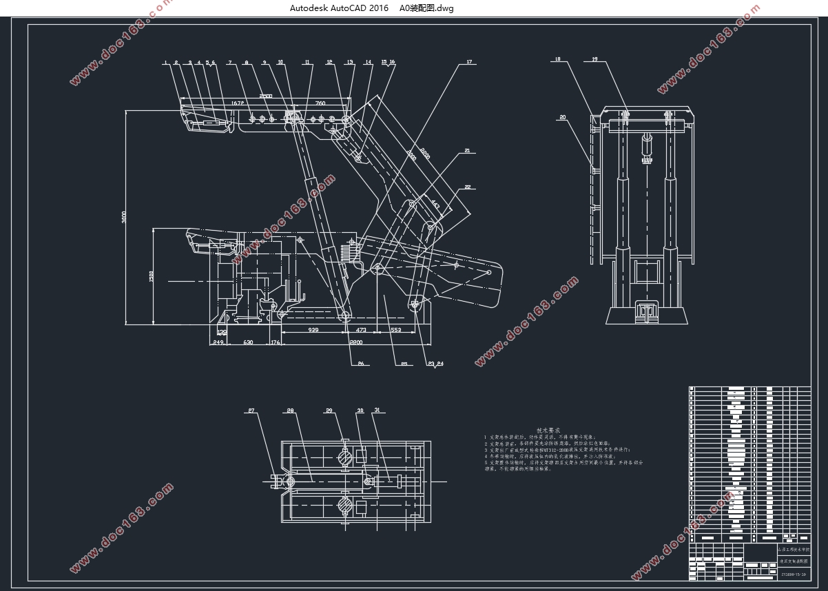
ZY3600-15-30液压支架设计(含CAD零件图装配图)

ZY3600-15-30液压支架设计(含CAD零件图装配图)(论文说明书22000字,外文翻译,CAD图7张)
摘 要
本论文主要阐述了掩护式支架的设计过程。设计内容包括:选架型、总体设计、主要零部件的设计、主要零部件的校核和液压系统的设计。支架必须能有效支护和控制顶板,并能实现支撑、切顶、移架和推移运输机等一整套工序。
支架采用正四连杆机构,以改善受力状况。顶梁、掩护梁、底座等均做成箱体结构;立柱采用带双伸缩双作用液压缸,以增加工作行程来满足支架调高范围的需要;推移千斤顶采用框架结构,以减少推溜力和增大移架力。校核按弯曲应力进行计算。液压支架与可弯曲输送机和采煤机组成综合机械化采煤设备,它的应用对增加采煤工作面产量、提高劳动生产率、降低成本、减轻工人的体力劳动和保证安全生产是不可缺少的有效措施。
关键词:掩护式;四连杆;双伸缩。
Design of ZY3600-15-30Hydraulic Support
Abstract
This article mainly expounds the design of the powered support for top-caving. The content mainly includes: the selection of form, design of the main parts and workpieces, the calculation of the strength of the main parts and workpieces, and the design of the powered system.The powered support must be able to support and control the roof effectively, and can realize supporting the roof, cutting the roof, advancing the support, and pushing forwards the conveyer , and so on.
[来源:http://Doc163.com]
The powered support adopts the upright four-link mechanism, in order to improve the mechanics condition. The roof beam, and the base and so on are done in chest structure; the stand post is a jack which have a single flex and double function with a lengthening pole, so as to lengthen the journey of the jack to satisfy the change of the height of the powered support. The “advancing and moving ”jack is done in frame-saw structure ,in order to minish the force pushing forwards the conveyer and increase the force advancing the powered support. The checking computation is done with the bending strain. The hydraulic pressure packing block with can curve the sonveyor and the coal winning machine composition comprehensive mechanization coal mining equipments, its application to increase coal mining working face output, raise to labor the rate of production and decline low cost, ease the worker's manual labor and assurances safe production is indispensable valid measure.
Key words: double flex lengthening pole;the powered support for top-caving; the upright four-link mechanism. [资料来源:https://www.doc163.com]
[来源:http://Doc163.com]


目 录
摘 要 i
Abstract ii
1 概 述 1
1.1 液压支架的用途、原理和分类 1
1.1.1 液压支架的用途 1
1.1.2 液压支架的动作原理 1 [资料来源:www.doc163.com]
1.1.3 液压支架的分类 3
1.2 对液压支架的要求和设计液压支架必要的基本参数 5
1.2.1 设计目的 5
1.2.2 对液压支架的基本要求 5
1.2.3 设计液压支架必需的基本参数 6
1.3 国内外液压支架的差距及今后的发展趋势 6
2 液压支架的选型和主要参数的确定 9
2.1 液压支架的选型 9
2.1.1 液压支架的选型 9
2.2 综采工作面设备的配套 11
2.2.1 采煤机、液压支架和运输机的配套 12
2.2.2 生产能力配套 12
2.2.3 性能配套 12
2.2.4 其他附属设备的配套 12
3 液压支架的整体结构尺寸设计 13
3.1 支架高度、支架间距、底座长度的确定 13
3.1.1 支架高度和支架的伸缩比 13 [资料来源:http://doc163.com]
3.2 四连杆机构的作用和四连杆机构设计 14
3.2.1 四连杆机构的作用 14
3.2.2 四连杆机构的设计 15
3.3 四连杆机构优选设计法 18
3.3.1 目标函数的确定 18
3.3.2 四连杆机构的集合特征 19
3.4 顶梁长度的确定 20
3.4.1 支架工作方式对支架顶梁长度的影响 20
3.4.2 配套尺寸对顶梁长度的影响 20
3.4.3 顶梁长度计算 20
3.5 确定立柱的技术参数 21
3.6 立柱的初撑力和泵站额定工作压力 22
3.7 立柱工作阻力的确定 22
3.8 立柱的支撑方式和柱窝位置的确定 23
3.8.1 支撑方式 23
3.8.2 立柱柱窝位置的确定 23
3.9 验算立柱的倾角 25
3.9.1 立柱最小倾角的验算 25
[资料来源:http://Doc163.com]
3.9.2 立柱最大倾角的确定 26
3.10 平衡千斤顶的参数及铰接位置的确定 26
3.10.1 平衡千斤顶拉力的计算 26
3.10.2 平衡千斤顶的推力计算 27
3.10.3 确定平衡千斤顶得缸径 28
3.10.4 平衡千斤顶铰接位置的确定 29
3.11 其他千斤顶技术参数的确定 33
3.11.1 推移千斤顶技术参数的确定 33
3.11.2 侧推千斤顶技术参数得确定 34
4 液压支架受力分析和计算 35
4.1 液压支架受力分析 35
4.2 确定顶梁载荷分布 39
4.3 支架支护效率 40
5 主要部件的尺寸确定及强度校核 41
5.1 立柱强度校核 41
5.1.1 立柱的稳定性验算 41
5.1.2 活塞杆强度校核 43 [资料来源:www.doc163.com]
5.1.3 缸体强度校核 44
5.2 各主要部件的尺寸确定 45
5.3 顶梁与掩护梁铰接用销轴的强度计算 45
5.4 顶梁上铰接平衡千斤顶用耳座的强度计算 46
5.5 掩护梁上铰接平衡千斤顶用耳座的强度计算 47
5.6 掩护梁上铰接平衡千斤顶用耳板的强度计算 48
5.7 铰接前连杆用销轴的强度计算 49
5.8 顶梁的强度计算 50
5.8.1 作出顶梁受力图、剪力图和弯矩图。 50
5.8.2 按弯曲应力进行强度校核 50
5.9 掩护梁强度计算 52
5.9.1 掩护梁受力如图5-7所示 52
5.9.2 计算截面积F及截面形心至a-a面的距离y和主惯性矩Jz 53
5.9.3 计算弯曲应力和安全系数 54
5.10 底座强度计算 54
5.10.1 计算截面积F及截面形心至a-a面的距离y和主惯性矩Jz 55
[资料来源:http://www.doc163.com]
5.10.2 计算弯曲应力和安全系数 56
6 液压系统设计 57
6.1 液压支架传动系统 57
6.1.1 液压支架传动系统的基本要求 57
6.1.2 液压支架的液压传动特点 57
6.2 液压支架的液压控制系统 58
6.2.1 液压支架的液压控制系统 59
6.2.2 工作原理 59
参考文献 61
外文文献 64
中文翻译 75
致 谢 83
下一篇:矿用200KW悬臂式掘进机截割部设计(含CAD零件图装配图)
