风电回转支承试验台驱动器:结构设计与校核(含CAD图)

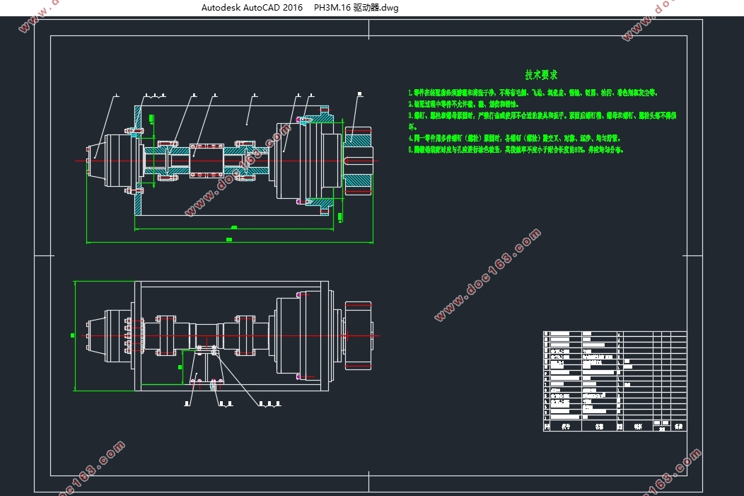
风电回转支承试验台驱动器:结构设计与校核(含CAD图)(论文说明书11000字,CAD图3张)
摘 要
回转支承作为风力发电机的核心部件,它的工作环境十分差,主要受到温差过大、雨水天气和风力方向与大小变化大等因素的影响,所以对性能要求非常高。因此,研究出完善的回转支承检测技术,设计出优秀的大型风电回转支承试验台,特别是回转支承试验台驱动器,对于国内回转支承技术的发展与提升有着巨大的作用。
本文根据所需试验回转支承的几何尺寸,进行试验台驱动器的结构设计并校核。根据被试件承载能力确定扭矩大小,选取合适的减速比,设计与回转支承的配对齿轮,再根据低速大扭矩的要求选取减速液压马达的型号,完成驱动器的整体框架结构设计。
关键词:回转支承 配对齿轮 低速大扭矩 减速器
Rotary supporting test bench for wind power:Structure design and check
Abstract
Slewing bearing as the core component of the wind turbine, its working environment is very poor, mainly by temperature difference is too large, rain weather and wind direction and size of the change and factors of influence, so the performance requirements is very high. Therefore, the research on the improvement of slewing bearing detection technology, design good large-scale wind power slewing bearing test rig, especially the slewing bearing test rig actuator, for the development and improvement of the technology of domestic slewing bearings has a great role.
[资料来源:Doc163.com]
In this article, the structure of the test bench is designed and checked according to the geometric size of the rotary support. According to the tested bearing capacity to determine the size of the torque, select the appropriate reduction ratio, design and slewing bearing the mating gear, based on low-speed high torque requirements selected design of reducer and hydraulic motor, drive up the overall frame structure design.
Keywords: slewing bearing,matched gear,low speed and high torque,retarder
[资料来源:www.doc163.com]


目录
摘 要 I
Abstract II
第一章 引言 1
1.1 回转支承的简介 1
1.2回转支承的研究现状 1
1.2.1 国外的研究现状 1
1.2.2 国内的研究现状 2
1.3 回转支承试验台驱动器设计的目的和意义 2
1.4 研究技术和科学方法 3
第二章 回转支承试验台驱动器的设计方案分析 4
2.1设计要求 4
[资料来源:Doc163.com]
2.1.1 试验台驱动器简述 4
2.1.2试验台加载要求 5
2.1.3 功能分析 6
2.2 配对齿轮的设计参数 7
2.2.1 压力角的选择 7
2.2.2 小齿轮齿数的选择 7
2.2.3 齿轮精度的选择 7
2.3 减速器的设计选择 8
2.3.1 减速器的种类 8
2.3.2 各种类减速器的特点 9
2.4 液压马达的选择 10
2.4.1 液压马达传动相比其他传动的优缺点 10
2.4.2 液压马达的分类 12
2.4.3 液压马达的选用原则 12
第三章 试验台驱动器的元件选型与校核 14
3.1 回转支承摩擦阻力矩的计算 14
3.1.1 回转支承摩擦阻力矩的估算 14
3.1.2 结果分析 14
3.2 驱动参数的确定 15
3.2.1 摩擦力矩的计算 15
3.2.2 旋转速度计算 15 [资料来源:http://www.doc163.com]
3.2.3 驱动器选型及相关参数计算 16
3.3 传动齿轮的设计与校核 16
3.3.1 传动齿轮的参数设计 16
3.3.2 传动齿轮的参数计算 16
3.3.3 传动齿轮的校核 18
第四章 驱动器的总体结构分析 24
4.1 总装图和部件装配图的设计概述 24
4.2 驱动器装配图的具体介绍 24
参考文献 27
致谢 29 [资料来源:http://Doc163.com]
