
心脏线轨迹直摆组合凸轮机构设计(CAD,Proe三维,仿真视频)
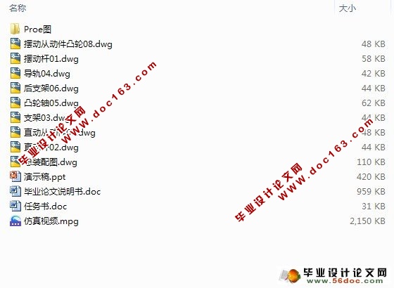
心脏线轨迹直摆组合凸轮机构设计(CAD,Proe三维,仿真视频)(任务书,论文说明书6500字,CAD图9张,Proe三维图,仿真视频,答辩PPT)
摘 要
本课题研究一直摆凸轮组合机构,该机构通过直动从动件凸轮机构与摆动从动件凸轮机构组成联动凸轮机构,能够将主动件的转动转化为从动件上某点沿预期的曲线轨迹并以预期的运动规律运动。该机构所能实现的轨迹多种多样,如正弦波曲线、内摆线、带停点曲线、人头像及金鱼图像等等。本课题所研究的直摆凸轮组合机构要实现的是一心脏线轨迹。
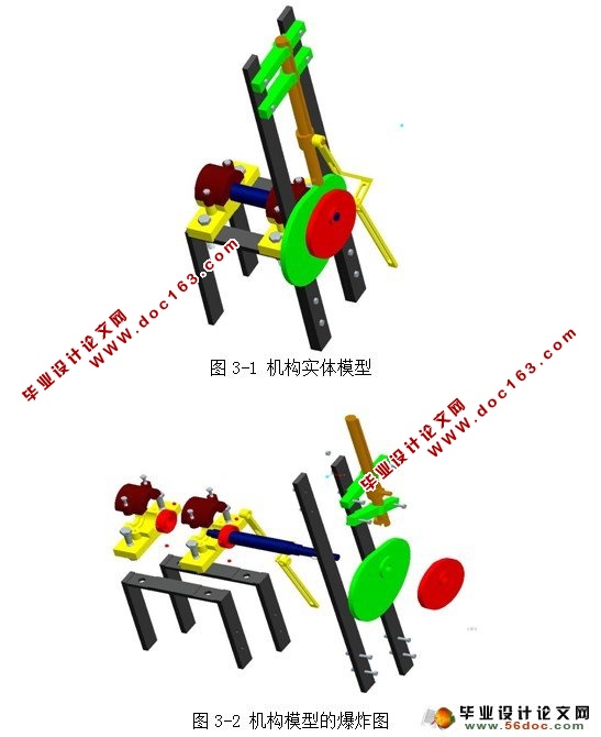
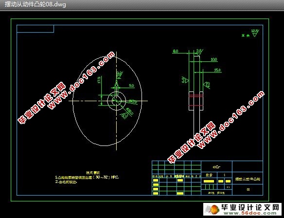
本课题首先通过理论分析,建立出了直、摆组合凸轮机构的设计公式,得出该机构各构件位置、大小及形状尺寸、凸轮实际廓线、理论廓线等。然后在此基础上对该机构的每一构件进行了实体设计,比如轴,导轨,支架等等的设计,并且对所设计的构件实体进行了装配组合。最后,为了验证设计的正确性,本课题还在Proe下对实体进行了运动仿真。
关键词:凸轮设计 组合机构 心脏线轨迹
THE DESIGN OF Z.B COMBINATORY CAM
MECHANISM TO GAIN ELIIPSE LOCUS [来源:http://www.doc163.com]
Abstract:The research portfolio has been put cam body parts through the straight moving follower cam cam with oscillating follower cam linkage institutions, able to take the initiative of the rotating pieces into a point on the follower along the expected curve trajectory and the expected movement of movements. The agency can track the realization of a wide range, such as the sine curve, with the cycloid, with stopping points, curves, images of goldfish heads and so on. Studied the subject before the straight cam combination mechanism is to achieve a heart-line trajectory.
First of all, this issue through theoretical analysis, a straight, before the design of cam combination formula, the components come to the location, size and shape of the size of the actual cam profile and theoretical profile and so on. And then on the basis of each component of the institution to carry out the physical design, such as shafts, rails, frame design, etc., and components designed for the assembly combination of entities. Finally, in order to verify the correctness of the design, the issue is still under Proe motion simulation entities. [资料来源:Doc163.com]
Key words: Cam Design Combination Mechanism Heart-line trajectory
[资料来源:http://Doc163.com]
 [资料来源:http://www.doc163.com]
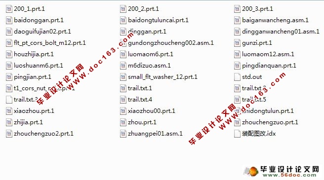
目 录
1 绪论 1
1.1直、摆组合凸轮机构的研究意义 1
1.2凸轮机构以及组合机构的研究和发展状况 2
1.3直、摆组合凸轮机构的研究方法 2
1.3.1直、摆组合凸轮机构的设计 2
1.3.2本课题的主要研究方法 2
2 直动从动机凸轮和摆动从动件凸轮的设计 4
2.1 直、摆组合凸轮机构设计基本思想 4
2.2直、摆组合凸轮机构设计步骤 5
2.2.1求取坐标点 5
2.2.2确定机构初始位置参数 6
2.2.3 确定顶杆位移与摆杆转角的变化规律 7
2.2.4 凸轮廓形设计 7
2.2.5直动从动件凸轮的顶杆长度及安装滞后角 11
2.3直动凸轮和摆动凸轮的实体设计 12
3 机构的实体设计 14
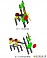
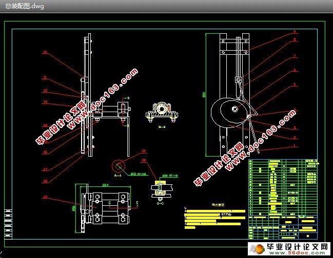
3.1 机构的实体结构 14
3.2 支架的设计 15
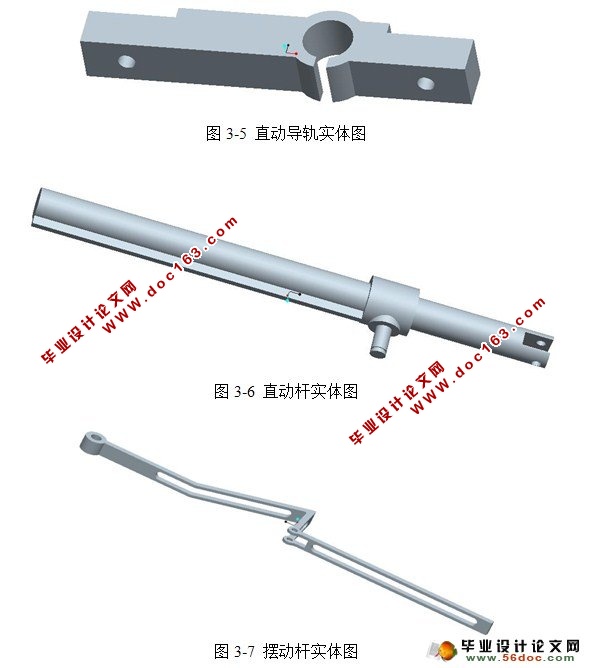
3.3 直动导轨的设计 16
3.4直动杆的设计 16
3.5摆动杆的设计 17
3.6轴系零部件的设计 17
3.6.1 拟定轴上零件的装配方案 18
3.6.2 确定轴的各段直径和长度 18
3.6.3轴上零件的周向定位 18
4 机构的运动仿真 20
参考文献 21
致谢 22
[资料来源:www.doc163.com]
上一篇:BB肥生产设备总体设计及机架设计
下一篇:双轴桨叶式高效混合机工作机构设计