
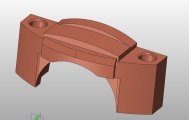
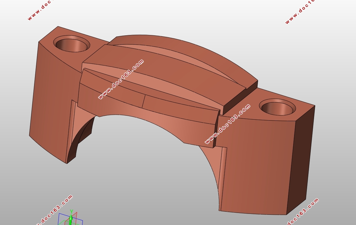
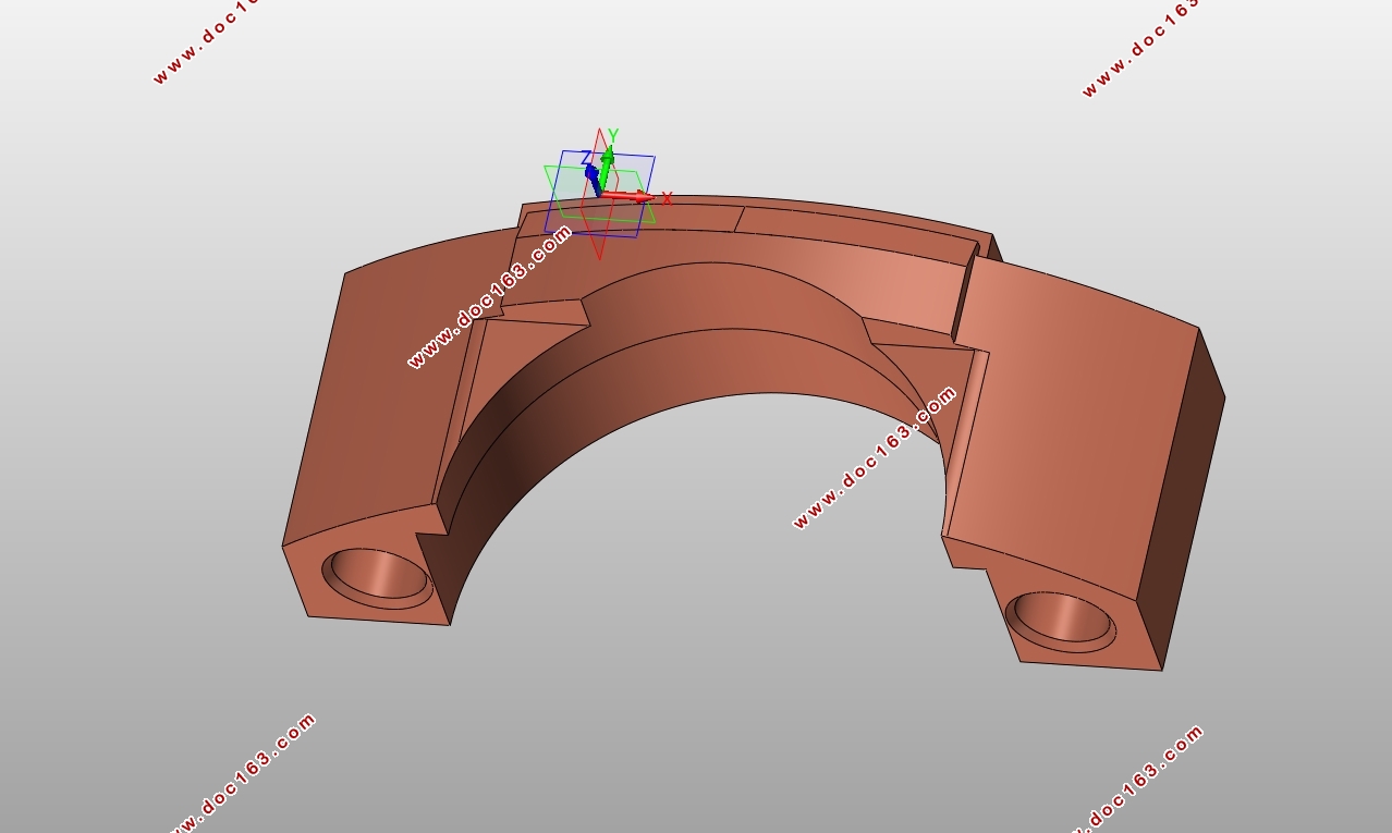
汽车后桥减速器轴承盖夹具设计(含SolidWorks三维图)
汽车后桥减速器轴承盖夹具设计(含SolidWorks三维图)(任务书,开题报告,外文翻译,论文说明书11300字,SolidWorks三维图)
摘要
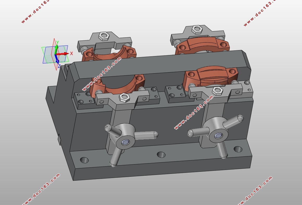
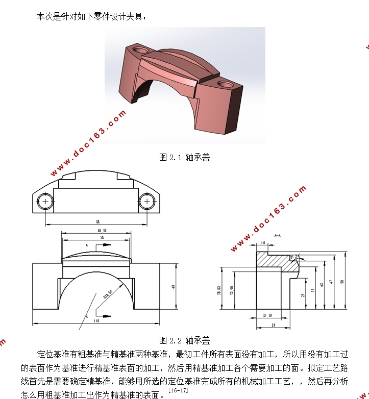
这次毕业设计的主要任务是完成减速器轴承盖夹具设计,内容是利用GKV900立式加工中心加工材料为QT450-10,零件硬度为HB180-220工件所需的手动夹具,加工的工序是粗精铣减速器轴盖底面、上面及钻扩2-φ12孔及倒角。设计纲领是按20000只/年,每年252天两班制,设备开机率85%进行设计。在说明书中详细的描述了减速器轴承盖的加工工艺和定位基准的选择,然后比较各种定位方案,选择出最合理的方案。确定定位所需要的定位元件以及计算定位误差,再计算切削力与夹紧力,确定切削力小于夹紧力。最后把各元件装配起来,详细介绍一下夹具的装配顺序与使用方法。
关键字:夹具;工艺;定位;基准;夹紧
Abstract
The graduation design of the main task is to complete the reducer bearing cap fixture design, the use of GKV900 vertical machining center processing materials for the QT450-10, parts hardness HB180-220 workpiece required for the fixture, the processing process is coarse grinding slow The bottom of the shaft cover, the top and drill 2 - φ12 hole and chamfer. Design program is based on 20000 / year, 252 days each year two classes, equipment operating rate of 85% of the design. In the manual in detail describes the reducer bearing cover processing technology and positioning the choice of benchmarks, and then compare the various positioning options, choose the most reasonable program. Determine the positioning elements needed to locate and calculate the positioning error, and then calculate the cutting force and clamping force to determine the cutting force is less than the clamping force. Finally, the components assembled together, detailing the fixture assembly sequence and use.
Key words: fixture; process; positioning; reference; clamping
[资料来源:http://www.doc163.com]
 [来源:http://Doc163.com]
目录
1绪论 1
1.1 机床夹具在机械加工中的作用 1
1.2 机床夹具种类 1
1.3 机床夹具的组成 2
1.4机床夹具的发展趋势 2
2减速器轴承盖的工艺规程的制定 3
[来源:http://Doc163.com]
2.1定位基准的选择 3
2.2减速器轴承盖的机械加工顺序的确定准则 4
2.3轴承盖表面加工方法的确定 6
2.3.1分析工件表面加工顺序 6
2.3.2确定工件加工工序 6
3夹具结构方案 7
3.1各加工表面的定位夹紧方案 7
3.1.1铣底平面定位方案 7
3.1.2铣台阶面的定位方案 8
3.1.3钻孔的定位方案 9
3.2定位元件的选择及定位误差的计算 9
3.2.1铣底平面的定位元件及定位误差计算 9
3.2.2定位误差计算 10
3.2.3铣台阶面夹具定位及定位误差计算 10
3.2.4定位误差计算 12
4夹紧机构的设计 14
4.1铣底平面的夹紧力及夹紧误差的计算 14
4.2铣台阶面夹紧力及夹紧误差计算 16
4.3螺旋夹紧机构的夹紧力计算 18
4.4夹紧机构元件的设计 19 [来源:http://www.doc163.com]
4.4.1压头、压板 19
4.4.2压杆、顶杆、回转螺钉 20
4.4.3拉杆 22
4.4.4手柄螺母和手柄 23
4.5夹具体的设计 23
4.5.1夹具座设计的基本要求 23
4.5.2夹具体毛坯的制造方法 24
4.5.3夹具座结构 24
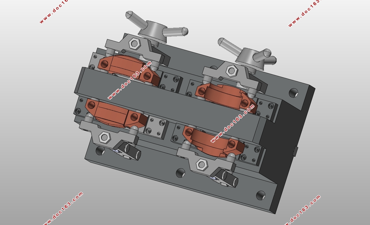
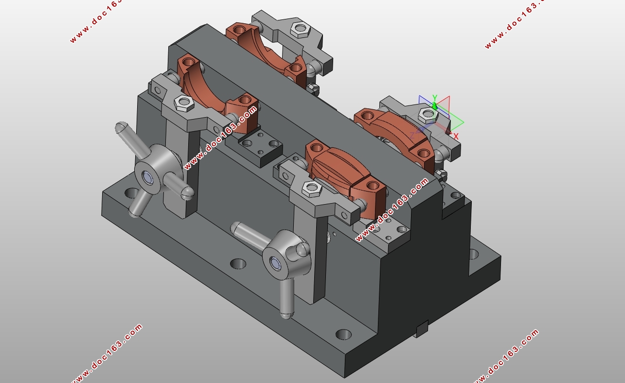
4.6夹具装配体 25
4.6.1装配顺序 25
4.6.2使用方法 25
4.6.3夹具与机床的连接 26
结论 27
致谢 28
参考文献 29 [来源:http://www.doc163.com]
上一篇:Φ38mm半轴端面粗铣夹具设计(含CAD图,CAXA图)