商务车离合器壳体T1、T2面铣削加工工艺装备设计(含CAD夹具图)

商务车离合器壳体T1、T2面铣削加工工艺装备设计(含CAD夹具图)(任务书,开题报告,论文说明书10000字,CAD图6张)
摘要
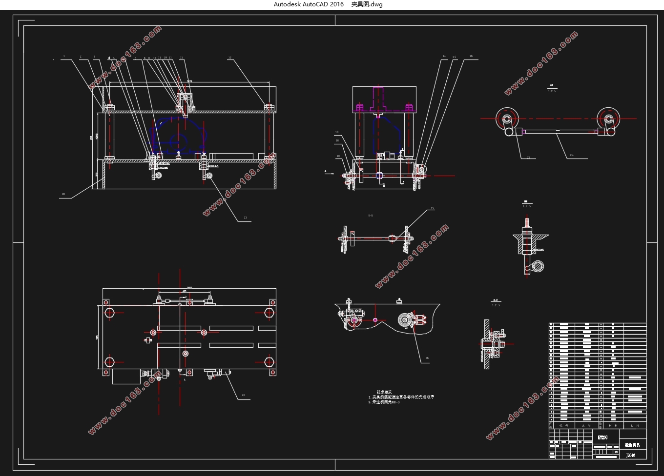
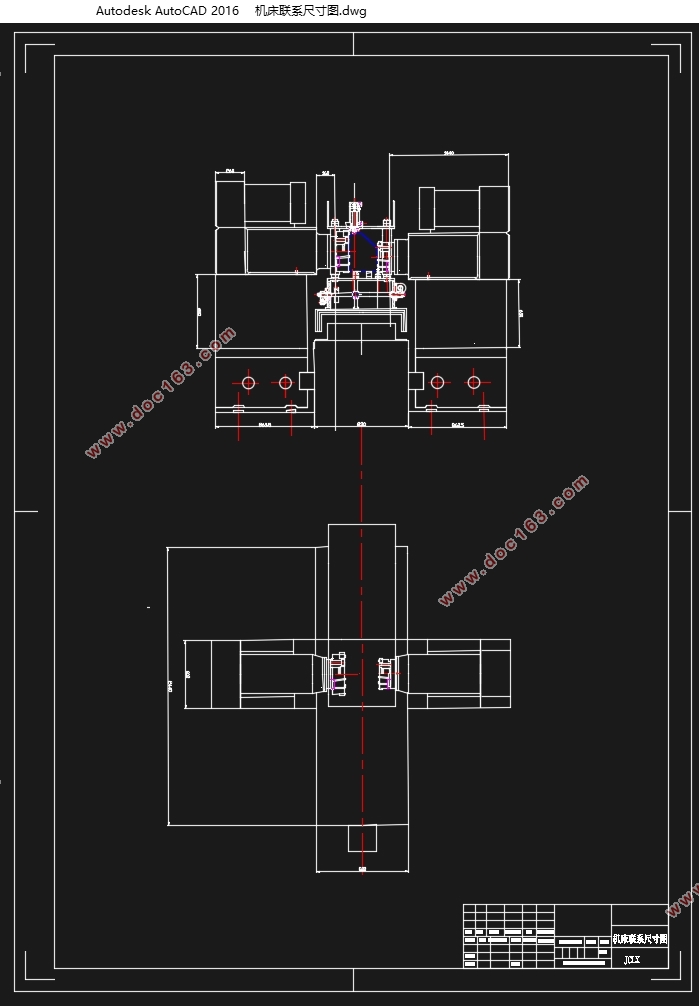
铣削组合机床是现今机械零件加工普遍使用的通用化、系列化机床,组合机床以不止一种配置方式是形式出现在人们面前,组合机床的主要功能是依据被加工零件的尺寸要求和精度要求选择合理的机床型式、规格以及精度等级,依据实际情况选择适用的通用组成部件,进行组装形成可以实现符合加工要求功能的机床。商用车离合器壳体T1、T2面铣削加工工艺装备设计主要内容是对离合器进行工艺分析,并设计T1、T2面铣削夹具以及组合机床。具体为对T1、T2面重点分析绘制工序图与加工示意图;通过两面一销定位设计液压缸夹紧夹具,定位销为液压驱动伸缩式,绘制装配图;设计铣削刀具以及组合机床,绘制机床联系尺寸图;完成生产率卡。通过液压缸夹紧既能保证夹紧力又能减少夹紧时间,提高效率;液压伸缩式定位销则确保定位的准确性以及加工精度要求,保证加工质量。整个夹具以及机床设计将大大缩短铣削时间,提高生产效率,完成生产任务。
关键词:三图一卡 加工总体工艺方案 组合机床 夹具
Abstract
Milling machine is a combination of modern machine parts widely used GSM of machine tools, combined machine tools in more than one configuration is in the form in front of people.Modular Machine Tool main function is to be based on size requirements and precision machined parts requirements reasonable choice of machine type, size and accuracy class.Based on the actual situation to select common components applicable,The assembly can be formed in line with the requirements of the processing functions of the machine.Commercial vehicle clutch housing T1, T2 face milling process equipment design is the main content of the clutch for process analysis and design of T1, T2 and face milling jig combination machine.Specifically for the T1, T2 focuses on surface rendering process diagram and schematic processing;Design hydraulic cylinders on both sides by a clamping jig positioning pin, pin telescopic hydraulic drive, assembly drawing;Design and combination of machine tools milling cutter, drawing machine contact dimension drawings; complete productivity cards.Clamped by a hydraulic cylinder can ensure the clamping force can reduce clamping time and improve efficiency;Hydraulic retractable locating pin is positioned to ensure the accuracy and precision requirements, the quality assurance process.The entire fixture and tool design will greatly shorten the milling time and improve production efficiency, to complete production tasks. [资料来源:Doc163.com]
Key words:Triple image a card Overall processing technology program
Modular Machine Tool Fixture
1.3设计内容
离合器壳体是汽车结构中的一个主要部件,主要起安装离合器,连接发动机与变速箱的作用,其加工质量直接影响汽车整车的工作性能。采用组合机床加工,生产批量:70,000件/年。
1.离合器壳体加工总体工艺方案设计
2.离合器壳体T1、T2面铣削加工组合机床设计
3. 离合器壳体T1、T2面铣削加工夹具设计
2.总体工艺方案设计
机床工艺方案是组合机床设计制造的基础,工艺方案的的制定将成为影响夹具设计,组合机床设计的关键因素,是进行组合机床设计不容小视的核心一步 ,它决定机床能否完成设计制造,决定机床设计完成后是否达到零件在加工效率以及加工精度方面的特殊要求,,是机床设计能否完美实现功能的核心要素。
[资料来源:http://doc163.com]


目录
1.绪论 6
1.1 国内外的研究现状分析 6
1.2研究目的 7
1.3设计内容 8
2.总体工艺方案设计 9
2.1离合器壳体加工工艺路线 9
2.2工序图 11
2.3 加工示意图 12
3组合机床设计 16
3.1铣床选择 16
3.2 铣削头的选择 16
3.3铣刀及辅具设计 17
3.4工作台选择 17
4.夹具设计 19
4.1定位方式 19
4.2夹紧方式 19
4.3液压缸以及液压伸缩式定位销的设计 20
4.4夹具的结构设计 22
参考文献 23
致谢 24
上一篇:C336主轴箱体加工镗模设计(含CAD零件图装配图,加工工艺过程卡)
下一篇:车床尾座体加工工艺及加工φ22孔夹具设计(含CAD零件图装配图)
