
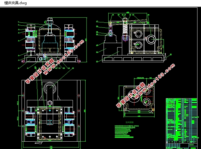
三孔双向卧式组合镗床夹具设计(含CAD夹具装配图)
三孔双向卧式组合镗床夹具设计(含CAD夹具装配图)(论文说明书9000字,CAD图纸2张)
摘 要
双向卧式组合镗床设计主要包括卧式单工位双面组合镗床传动系统图的设计和多轴箱设计、夹具、刀具导向装置的设计和夹紧装置的选择。卧式单工位双面组合镗床传动系统图的设计和多轴箱设计、夹具、刀具导向装置的设计和夹紧装置的选择是组合机床的主要组成部分,是保证加工精度的关键部件。它和机床的其它部分有着及其密切的联系。因此,要求组合机床必须具有良好的刚性和足够的夹紧力,以保证在整个加工过程中工件不产生位移。同时,满足工件加工的各项技术要求,要保证工件不允许的变形,提高生产率和降低生产成本,工艺性和实用性要好。
由加工零件的工艺条件为粗镗,因此采用两面同时镗削,不仅加工方便,而且生产效率较高,因此采用双面卧式组合镗床进行加工是合理的。
根据加工零件的加工特点,选择一面两孔作为定位基准,限制工件在加工时的六个自由度。为了确保定位精度和稳定性,采用底平面定位。定位销采用手动回转机构定位销,用支承板定位系统,它用油缸经过推杆和一系列杠杆实现定位销的插入和拔出。
关键词:双向卧式组合镗床,传动系统,导向装置,粗镗,一面两孔 [来源:http://www.doc163.com]
ABSTRACT
CK-ⅡNumerically-controlled machine tool headstock horizontal type two-sided combination boring lathes and jig design
ABSTRACT
The bidirectional horizontal-type combination boring lathe design mainly includes the horizontal-type single location two-sided combination boring lathe kinematic scheme the design and the multi-axle-box design, the jig, the cutting tool guide design and the clamp choice. The horizontal-type single location two-sided combination boring lathe kinematic scheme's design and the multi-axle-box design, the jig, the cutting tool guide's design and clamp's choice is aggregate machine-tool's key component, is guarantees the working accuracy the key component. It and engine bed's other parts has and the close relation. Therefore, the request aggregate machine-tool must have the good rigidity and the enough clamping force, guaranteed that the work piece does not have the displacement in the entire processing process. At the same time, satisfies the work piece processing each specification, must guarantee the work piece does not permit the distortion, raises the productivity and reduces the production cost. The technology capability and the usability is friends with. by the processing components' technological conditions is the thick boring, therefore uses at the same time both sides boring, not only processes conveniently, moreover the production efficiency is high, therefore uses the two-sided horizontal-type combination boring lathe to carry on the processing is reasonable.
According to the processing components' processing characteristic, choice two take the localization datum at the same time, the limit work piece in processing time six degrees-of-freedom. In order to guarantee that the pointing accuracy and the stability, use the bottom plane localization. The positioning pin uses the manual swiveling mechanism positioning pin, with the support plate positioning system, it uses the cylinder realizes positioning pin's insertion after the throwout lever and a series of release levers and draws out.
KEY WORDS: The bidirectional horizontal-type combination boring lathe,kinematic scheme,the cutting tool guide,the thick boring,two take the localization datum
该方案是三孔双向卧式组合镗床夹具设计,双向卧式组合镗床设计主要包括卧式单工位双面组合镗床传动系统图的设计和多轴箱设计、夹具、刀具导向装置的设计和夹紧装置的选择。卧式单工位双面组合镗床传动系统图的设计和多轴箱设计、夹具、刀具导向装置的设计和夹紧装置的选择是组合机床的主要组成部分,是保证加工精度的关键部件。它和机床的其它部分有着及其密切的联系。因此,要求组合机床必须具有良好的刚性和足够的夹紧力,以保证在整个加工过程中工件不产生位移。同时,满足工件加工的各项技术要求,要保证工件不允许的变形,提高生产率和降低生产成本,工艺性和实用性要好。 [资料来源:Doc163.com]
由加工零件的工艺条件为粗镗,因此采用两面同时镗削,不仅加工方便,而且生产效率较高,因此采用双面卧式组合镗床进行加工是合理的。
根据加工零件的加工特点,选择一面两孔作为定位基准,限制工件在加工时的六个自由度。为了确保定位精度和稳定性,采用底平面定位。定位销采用手动回转机构定位销,用支承板定位系统,它用油缸经过推杆和一系列杠杆实现定位销的插入和拔出。
[资料来源:Doc163.com]


目 录
前 言 1
[来源:http://Doc163.com]
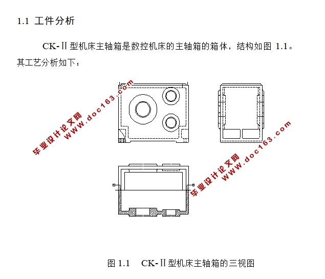
第1章CK-Ⅱ型机床主轴箱产品工艺过程分析 3
1.1 工件分析 3
1.1.1 木模 3
1.1.2造型 3
1.1.3浇注: 3
1.1.4 清砂: 4
1.1.5 退火: 4
1.1.6 刷涂料: 4
1.1.7 钳: 4
1.1.8 龙门铣: 4
1.1.9 龙门刨: 4
1.1.10 摇臂钻: 4
1.1.11 粗镗: 4
1.1.12 精镗: 5
1.1.13 钳: 5
1.1.14 检验: 5
1.1.15 钳: 5
1.1.16 入库: 5
第2章CK-Ⅱ型数控机床粗镗工序及组合镗床总体设计 6
2.1 CK-Ⅱ型数控机床主轴箱粗镗工序分析及其机床类型选择 6
2.1.1 本工序采用的定位方案及特点 6
2.1.2 本工序应达到的技术要求 6
2.2确定确定运动参数和动力参数 7
2.2.1 确定切削用量 7
2.2.2确定机床动力参数 (切削力、切削转矩、切削功率)及刀具耐用度 8
2.3绘制加工示意图 8
2.3.1选择刀具 8
2.3.2确定导向装置 9
2.3.3 .支架和底座 10
2.3.4 计算动力部件的工作循环及工作行程 10
第3章 工件夹紧机构和夹紧力计算 13
3.1 夹紧机构的要求 13
3.1.1 夹紧力的方向应保证工件的既定位置而不破坏定位 13
3.1.2 夹紧力方向使工件变形最 13
3.2夹紧力的大小。 13
第4章 定位元件的选择以及计算 17
4.1 定位基准的选择 17
4.1.1 采用一面两销定位 17
4.1.2 工件以孔定位和以平面定位的分析 17
4.2 定位误差分析计算 18
4.2.1 定位件的选择 18
4.2.2 定位误差的计算 19 [资料来源:http://www.doc163.com]
第5章 夹具的发展前景 21
5.1 夹具的动向 21
5.1.1 高精 21
5.1.2 高效 21
5.2 夹具的最终形式 22
5.2.1 模块、组块 22
5.2.2 通用、经济 22
结 论 23
谢 辞 24
参考文献 25
下一篇:车床小刀架机械加工工艺及镗孔的夹具设计(含CAD零件图装配图)