
基于FPGA的数据采集卡设计
基于FPGA的数据采集卡设计(任务书,开题报告,论文12000字)
摘要
数据采集卡的功能是将模拟信号输入,然后转化成数字信号并且加以已处理,最终输出,是信息传递和处理系统的重要组成部分。
本次设计是基于FPGA进行的设计,FPGA配置具有很高的灵活性,还有丰富的IP核资源,很大程度上简化了存储模块的读写。本次使用DE1-SOC 开发板加扩展模块组成试验箱进行设计,芯片是Cyclone V系列的5CSEMA5F31C6芯片,板上集成有DDR控制器,外接DDR3颗粒(1GB)。HPS和FPGA通过内部的桥接可以实现相互访问,最大访问空间为1GB,速度最高可达800MHz (1600Mbps)。试验箱中还有12bit高精度ADC作为模数转换的核心模块,可以实现射频、中频模拟信号放大、滤波以及采样等各种功能的处理。软件编程使用QuartusII软件,编辑VHDL语言实现对硬件电路的逻辑控制,实现设计所需要的功能。
关键词:FPGA;数据采集卡;DE1-SOC 开发板;Quartus II
Abstract
The function of the data acquisition card is to input the analog signal, and then converted into a digital signal and processed, the final output, information transmission and processing system is an important part.
[资料来源:Doc163.com]
This design is based on FPGA design, FPGA configuration has a high flexibility, there are a wealth of IP core resources, largely simplifies the memory module read and write. The use of DE1-SOC development board plus expansion module composed of test chamber design, the chip is Cyclone V series 5CSEMA5F31C6 chip, integrated on the board with a DDR controller, external DDR3 particles (1GB). HPS and FPGA through the internal bridge can achieve mutual access, the maximum access space of 1GB, the speed of up to 800MHz (1600Mbps). Test box there are 12bit high-precision ADC as the core module of analog-to-digital conversion, can achieve RF, IF analog signal amplification, filtering and sampling and other functions of the treatment. Software programming using Quartus II software, edit the VHDL language to achieve the logic of the hardware circuit control, to achieve the design of the required functions.
Key Words:FPGA ;Data acquisition card ;DE1-SOC development board ;QuartusII
[资料来源:https://www.doc163.com]
目录
摘要 I
Abstract II
第1章绪论 1
1.1 课题研究背景及意义 1
1.2课题研究目的 2
1.3 国内外研究现状 2
1.4 课题研究内容 3
第2章课题研究相关技术 4
2.1 了解FPGA 4
2.2 了解Quartus II 5
2.2.1 Quartus II新建工程 5
2.2.2 下载至芯片流程 6
第3章系统设计 7
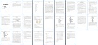
3.1 系统结构与框架 7
3.2 试验箱介绍 8
3.3 芯片选择 9
第4章软件设计 11
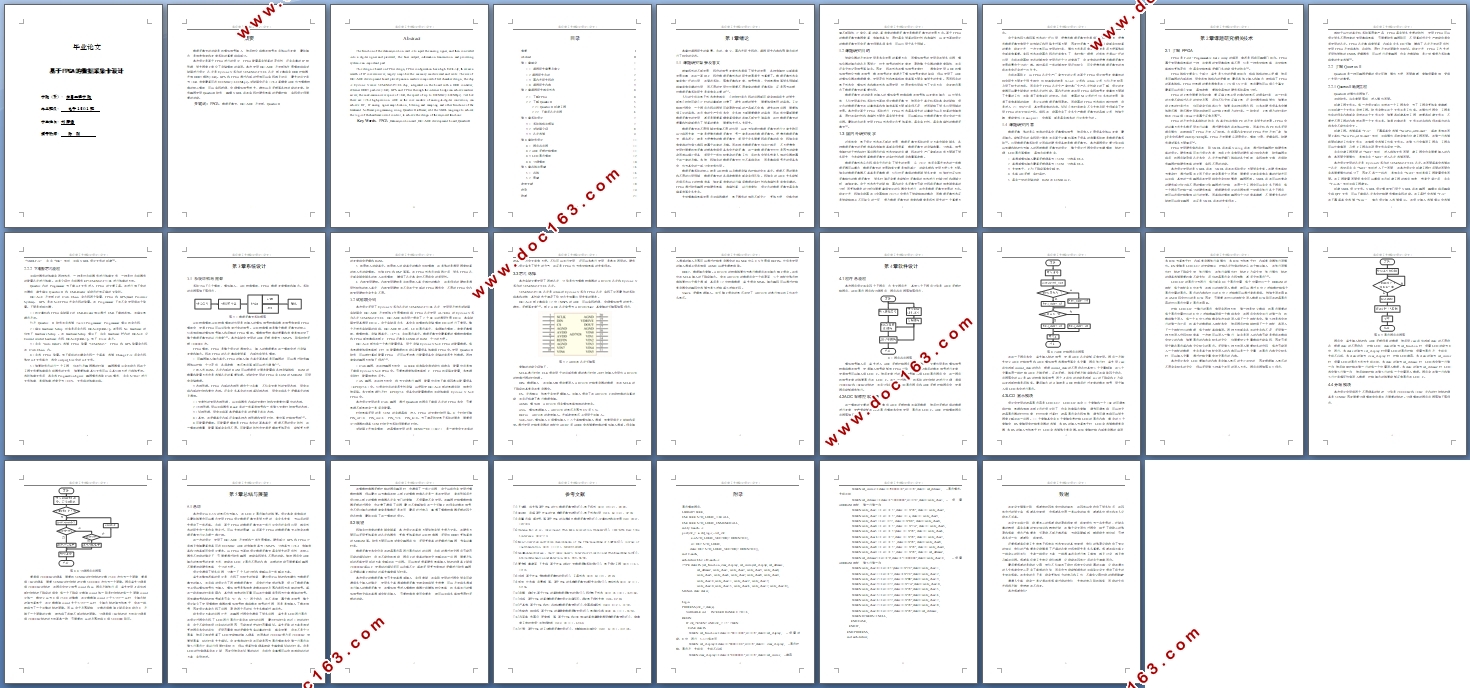
4.1 程序总流程 11 [资料来源:Doc163.com]
4.2 ADC采样控制模块 11
4.3 LCD显示模块 12
4.4 分频模块 14
第5章总结与展望 16
5.1 总结 16
5.2 展望 17
参考文献 18
附录 19
致谢 21 [版权所有:http://DOC163.com]