
智能浇花器的设计
智能浇花器的设计(任务书,开题报告,论文15800字)
摘要
自动浇花系统可以检测它所处的环境中的温度还有空气湿度。检测好后,检测器会把数据传送到微处理器上。经过MCU程序处理后,用电信号控制相应模块进行工作。
这个过程是实时的,检测器不停地测,测好后会立即输入到控制器中,控制器也会立即处理来执行命令。而导致的环境的改变也会立即被检测到,直到环境温度与湿度处在正常范围内。用数字电路控制水泵与风扇,实现土壤的湿润与干燥。
程序中规定的湿度值,是用来确定是否需要浇水或者干燥的参考值。湿度控制部分,通过按键设定合理的湿度上下限。如果检测到的湿度过于潮湿,那么主控制器就会发出电信号,浇水的信号灯亮,电磁阀吸和,开始浇水,同时通过DHT-11进行湿度的实时采集,当湿度回到固定范围内时,水泵自动停止浇水。若测得的湿度值超过上限,则干燥的信号灯亮,风扇转动,开始进行干燥,当湿度值降到正常范围内时,风扇自动停止转动。
关键词:DHT-11温湿度传感器 LCD1602液晶显示屏 STC89C51单片机 实时采集系统 C语言
The design of intelligent plant watering system
Abstract [资料来源:www.doc163.com]
In the design of automatic plant waterier, sensor technology and MCU control technology were used, to build a system which can collect temperature and humidity of soil and can carry out a real-time control.
In this design a digital circuit was used to control a pump and a fan and then achieve the moist or dry of soil. The entire system consists of two parts. The first part is the measurement and display of temperature and humidity. A DHT-11 is used to be the sensor, which detect the temperature and humidity of soil and then send the value into the microcontroller.
The microcontroller will process the value and then it will be sent to the LCD1602 Display from I/O output of the microcontroller. Meanwhile the humidity is the reference value used to determine whether to water or dry the soil. The second part is a humidity control part,which use a button to set a reasonable upper and lower limit of humidity. If the measured humidity exceeds the lower limit, the MCU sends out a digital signal, the LED of watering will be lit, and the solenoid valve will be going to control the pump to work. Meanwhile use DHT-11 to achieve a real-time collection of humidity. When the humidity goes back to the normal range, the pump will stop watering at once. If the measured humidity exceeds the upper limit, the LED of drying will be lit, and the solenoid valve will be going to control the fan to work. When the humidity goes back to the normal range, the fan will stop watering at once. [资料来源:www.doc163.com]
Keyword: DHT-11 temperature and humidity sensor; LCD1602 Display; STC89C51 microcontroller; real-time collection; C51 program


[资料来源:www.doc163.com]
目录
摘要 I
ABSTRACT II
第一章 绪论 1
1.1 研究的目的和意义 1
1.2 诞生背景及国内外发展现状 1
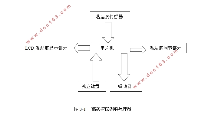
1.3 智能浇花器的系统设计 2
1.4 内容安排 2
第二章 系统方案分析与选择论证 3
2.1 系统方案设计 3
2.1.1 微处理器方案 3
2.1.2 温湿度检测模块 3
2.1.3 显示模块方案 4
2.1.4 报警模块方案 4
2.1.5 状态指示模块方案 4
2.1.6 继电器方案 4
2.2 最终决定方案 4
第三章 智能浇花器的硬件设计 5
3.1 单片机主控系统电路设计 5
3.1.1 STC89C51单片机 5
3.1.2 外部晶振时钟电路设计 6
3.1.3 复位电路设计 7
3.2 按键及读数原理 8
3.2.1 按键电路 8
3.2.2 SW-PB开关原理图 9
3.2.3 按键抖动的处理 9
3.3 LCD1602显示模块 10
3.3.1 LCD1602的基本数据 10
3.3.2 LCD1602的引脚说明 11
3.3.3 LCD1602的控制指令 11
3.4 温湿度检测模块 12
3.4.1 湿度的单位RH 12
3.4.2 DHT11的结构与性能 12
3.4.3 DHT11的工作原理 13
3.4.4 数据的采集与发送 13
3.5 继电器模块 14
3.5.1 继电器中三极管的作用 14
3.5.2 继电器的工作过程 14
3.6 防盗报警模块 15
3.6.1 蜂鸣器介绍 15
3.6.2 报警模块电路 15
3.7 LED灯状态指示模块 16
3.8 DC电源插口模块 17
第四章 智能浇花系统的软件设计 18
4.1 软件开发的环境 18
4.2 各模块程序设计 18
4.2.1 系统工作流程 18
4.2.2 LCD显示模块 19
4.2.3 温湿度处理模块 21
4.2.4 按键处理子程序 23
4.2.5 继电器模块流程 26
第五章 系统调试与分析 27
5.1程序的烧录 27
5.1.1 H1032的介绍 27
5.1.2 烧录过程 28
5.1.3 烧录遇到的问题 28
5.2 分模块调试 29
5.2.1 LCD1602液晶显示的检测与调试 29
5.2.2 温湿度采集模块的检测与调试 29
5.2.3 LED灯的状态指示检测与调试 29
5.2.4 报警电路的检测与调试 29
5.2.5 继电器的检测与调试 29
5.3 整体电路的调试 30
第六章 总结与展望 31
6.1 总结 31
6.2 展望 31
致谢 32
参考文献 33
程序 35
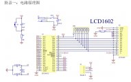
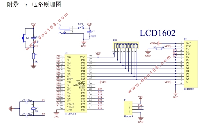
附录一:电路原理图 43
附录二:PCB图 44
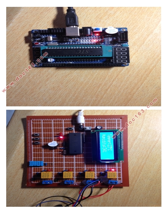
附录三:系统运行 45 [资料来源:www.doc163.com]