
60+100+60m预应力混凝土连续梁桥主跨桥设计(含CAD图)
60+100+60m预应力混凝土连续梁桥主跨桥设计(含CAD图)(开题报告,外文翻译,论文计算书18000字,CAD图14张)
摘 要
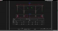
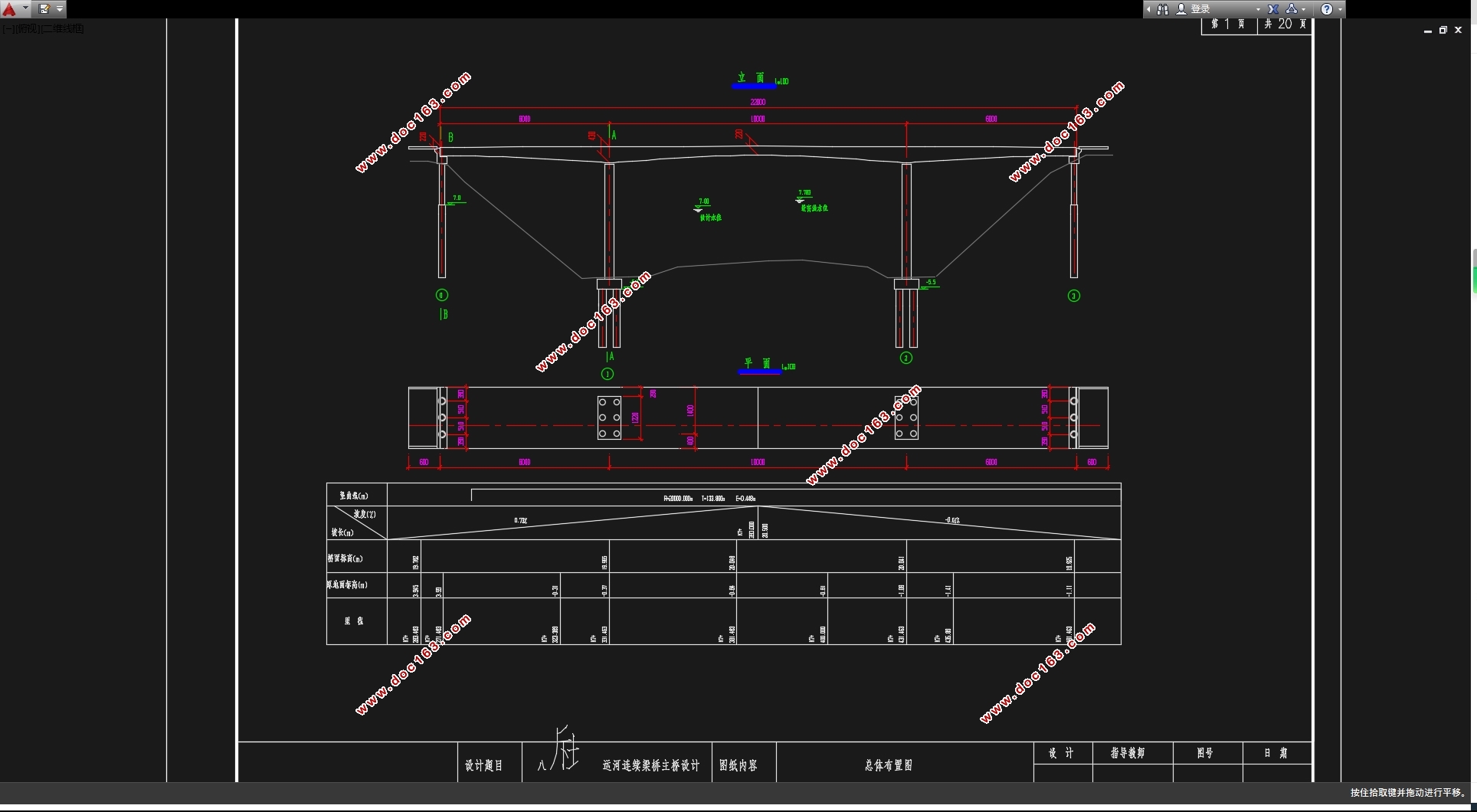
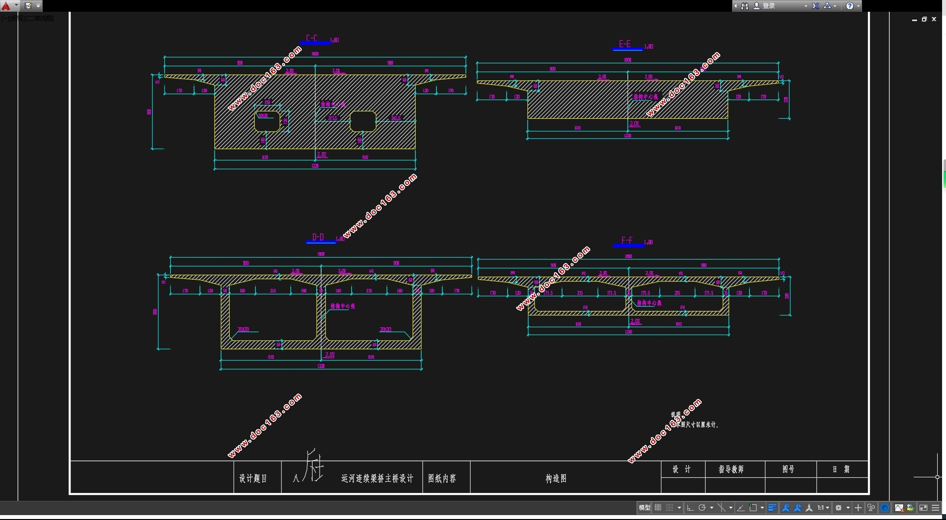
本次设计选用公路桥梁类型,道路类型为高速公路,桥梁取双向四车道行车,设计桥梁的跨度为60+100+60m,采用的是单箱双室箱型。桥宽18m主梁采用悬臂挂篮施工。
预应力混凝土连续梁桥以结构受力性能好、变形小、伸缩缝少、行车平顺舒适、养护工程量小、抗震能力强等而成为最富有竞争力的主要桥型之一。
根据活载位置的不同,刚构桥的断面可能出现正弯矩或负弯矩,当桥跨增大时,桥的支点截面处将承受较大的负弯矩,从绝对值来看,支点负弯矩远大于跨中正弯矩。因而,要按弯矩变化的幅值布置预应力钢筋。且多采用变截面梁,这样更能适应结构的内力分布规律和施工时的内力状态。
梁高按二次抛物线变化,从桥墩处最大6.0米到跨中2.2米,顶板厚度为25cm。为了减小施工难度,并结合连续梁桥的受力特点,底板厚度呈二次抛物线变化,由支点处向跨中减小。在设计好截面的基础上,对结构进行了内力分析(运用Midas),然后对钢筋数量进行估计并配置钢筋,进行预应力损失和次内力的计算,再检算主要控制截面的承载能力和变形情况,最后对主要工程量进行了估算。在做完所有的计算后,绘制结构施工图,包括桥跨布置图、施工程序图等,进行外文翻译,最后编制设计计算说明书及文档整理。
关键词:预应力混凝土连续梁桥、次内力、抛物线、悬臂施工、Midas。
Abstract
This for bridge is used in the highway, The spans of the bridge are 60+100+60 meters. It has a the box section of single case with double room and 18-meters wide. The road of the bridge serves four lanes. The girder applies cantilever hung-basket bearing and symmetric equilibrium construction.
The prestressed concrete continuous girder bridge become one of main bridge types of the most full of competion ability because of subjecting to the dint function with the structure good, having the small defomation, few of control joint,going smoothly comfort,protected the amout of engineering small and having the powerfully ability of earthquake proof and so on.
Because of the different position of the live load, positive bending moment or negative bending moment may appear at the same section of the bridge. Therefore, the disposition of the prestressed steel bar should adapts to the bridge’s bending moment. Bridge is composed of the continuous beam bridge and the pier with thinner wall. It not only keeps the advantages of the continuous beam bridge, but also saves the support at the same time. It reduces the quantity of the pier and foundation, and improves structural performance under the horizontal load, that is to say every flexible pier gains corresponding horizontal force according to its rigidity。
[来源:http://www.doc163.com]
The highness of the beam ranges from 6.0m at the piers to 2.2m at the middle of the span, changing at a quadratic parabolas path. The thickness of the roof is 25cm.In order to reduce the difficulty of construction and consider the character of the bridge under the loads, thickness of the baseplate minishes from the support to the middle of the span at a quadratic parabolas path. At the basis of the designing section, internal force analysis is done (by Midas).The amount of the steel bar is estimated and the collocation is done. After these processes, prestressing force loss and the secondary force can be calculated .Then, check whether the carrying capability and deflection of main controlling section can passes its limits. At last, the major amount of the project is estimated. After all the calculation, draw the construction drawing (including bridge span arrangement, construction procedure and so on), do the translation of foreign language. At last make the introduction of my design and sort my text file. [资料来源:www.doc163.com]
Key words:The prestressed concrete continuous girder bridge, secondary force, parabolic curves, cantilever hung-basket bearing, Midas.
由于苏南运河航道整治,全线要求达到Ⅲ级航道标准,要求通航净空满足80×7m要求。老桥通航净宽不满足80m要求,需拆除重建。考虑未来吴江市城市主干线东西干线的顺接通行要求,将新建桥梁桥位北移约2km,并提高原有桥梁设计标准重建。未来八坼桥梁规划桥宽为双幅共36m,现阶段实施单幅18m,现阶段实施桥梁采用双向4车道机非混行车道,路线线形设计预留100km/h时速标准,两侧设置防撞护栏。
采用设计流量
设计水位
桥位河段为VI-(1)级航道
桥位河段无凌汛、流冰
根据《水文学》相关章节计算得出
桥孔长度220m
桥面高程20.0m
桥墩最低冲刷线高程23.25m
2.2工程地质资料
地质经钻探资料分析,桥位处地基各土层状况为灰褐色粉质粘土、灰色淤泥质粉质 粘土、黄褐色粘土夹粉质粘土、灰-绿色粉质粘土、未风化的花岗岩。
表2-1 地基土质参数表
土层编号 土层名称 层底埋深(m) 层厚(m) γ(kN/m3 ) e w(%) IL c(kPa) φ(o) ES(MPa) fk(kPa) ps(MPa)
1 亚粘土 10.1 10.1 18.4 0.90 33 0.95 16.7 21.1 5.4 125 0.72
2 中细砂 22.1 12.0 17.8 1.06 34 1.10 14.2 18.6 3.8 95 0.86
3 中砂 27.4 5.3 19.1 0.88 30 0.70 18.4 23.3 11.5 140 3.44
4 圆砾混卵石 31.9 4.5 19.7 0.72 26 0.46 36.5 26.8 8.6 210 2.82 [来源:http://www.doc163.com]
5 未风化的花岗岩 >31.9
[资料来源:www.doc163.com]
 [资料来源:Doc163.com]

目录
摘 要 I
Abstract II
目录 0
第一章 绪论 1
第二章 基本设计资料 2
2.1 工程概况和背景 2
2.2工程地质资料 2
2.3设计依据 3
2.4设计技术标准和主要材料 4
2.4.1设计标准 4
2.4.2主要材料 4
2.5桥梁设计的基本要求 5
[资料来源:http://doc163.com]
2.5.1使用上的要求 5
2.5.2经济上的要求 5
2.5.3 结构和尺寸上的要求 5
2.5.4施工上的要求 5
2.5.5美观上的要求 5
第三章 桥型方案比选 6
3.1比选方案拟定 6
3.2 方案比选 7
第四章 桥梁上部结构设计与计算 9
4.1 主梁设计 9
4.1.1 主梁构造设计和基本尺寸。 9
4.1.2桥面铺装 10
4.1.2 主梁梁段的划分 11
4.1.3 主梁的预应力体系 11
4.2 下部结构设计 11
4.2.1桥墩构造形式及截面尺寸拟定 11
4.2.2 桥墩基础形式 11
4.3 主梁计算 12
4.2.1 主梁施工方案拟定 12
4.2.2施工阶段设计计算 12
4.2.3 基本参数的确定 12
4.2.4结构建模及添加荷载 13
[版权所有:http://DOC163.com]
4.4主梁内力计算和荷载组合 13
4.4.1一期自重作用效应计算。 15
4.4.2二期自重作用效应计算。 16
4.4.3温度次内力 17
4.4.4 基础沉降内力计算 20
4.4.4 移动荷载内力计算。 22
4.4.5主梁作用效应汇总。 23
4.4.6主梁内力组合 26
4.2.6预应力钢筋的估算 29
4.2.7 钢束应力损失计算 33
第五章 下部结构设计计算 39
5.1桥墩设计计算 39
5.2 基础计算 40
5.2.1 桩基础设计计算 40
5.2.2 承台设计计算。 46
第六章 抗裂验算 47
6.1规范要求 47
6.1.1正截面抗裂验算 47
6.1.2斜截面抗裂验算 49
第七章 持久状况构件的应力验算 51
7.1正截面混凝土压应力验算 51
7.2预应力筋拉应力验算 53
第八章 正常使用极限状态计算 58
8.1使用阶段挠度计算 58
8.2斜截面抗剪承载力计算 58
结论 60
参考文献 61
谢辞 62 [版权所有:http://DOC163.com]
上一篇:80+100+80m的三跨变高度连续梁桥设计(含CAD图)
下一篇:35+60+60+35m预应力混凝土刚构连续组合梁桥施工图设计(含CAD图)