
三跨预应力混凝土(65+120+65)m连续梁桥设计(含CAD图)
三跨预应力混凝土(65+120+65)m连续梁桥设计(含CAD图)(任务书,开题报告,外文翻译,论文说明书11000字,CAD图6张)
摘要
本设计的主要内容是预应力混凝土连续梁桥的设计,该桥位于某绕城高速公路上,主要设计桥梁的上部结构,设计荷载采用中—活载。
本设计采用方案为预应力混凝土连续梁桥,其桥型布置为65+120+65m,全长为250m,主梁采用变截面的单箱单室箱形截面,施工方法则采用悬臂施工法。本毕业设计使用midas 软件运行分析,考虑施工过程中的体系转换以及混凝土收缩徐变等因素来进行恒载内力计算。具体内容包括,计算各控制截面的内力影响线,并按最不利情况进行加载,得到活载作用下的内力包络图。基础沉降组的定义,在最不利组合情况下的计算得到的由基础沉降引起的最不利内力。根据规范与实际情况来选取截面梯度温差数据,并计算由温差引起的结构内力。通过荷载组合,得到结构组合内力的包络图。根据各控制截面内力进行了估束和配筋计算,并绘制了桥梁的梁体钢束位置图。最后,对各个控制截面进行了强度、抗裂性、应力和变形验算,各项验算均满足规范对预应力结构的要求。
关键词:连续梁;内力计算;预应力混凝土;检算;
Abstract [资料来源:http://doc163.com]
The main content of this design is the design of the prestressed concrete continuous girder bridge. The bridge is located on a highway around the city. It mainly designs theupper structure of the bridge and the design load adopts medium-live load.
This design adopts a prestressed concrete continuous beam bridge with a bridge type layout of 65+120+65m and a total length of 250m. The main beam adopts a single-box single-box box section with variable cross-section. The construction method adopts the cantilever construction method. The graduated design uses the midas software to run the analysis and consider the factors such as the system conversion during the construction process and the shrinkage and creep of concrete to calculate the constant load internal forces. The specific contents include calculating the internal force influence lines of each control section and loading them according to the most unfavorable conditions to obtain the internal force envelope diagram under live load action. The definition of the basic settlement group, the most unfavorable internal force caused by the foundation settlement calculated in the most unfavorable combination. According to the specification and actual conditions, the temperature gradient data of the cross section was selected, and the structural internal force caused by the temperature difference was calculated. Through the load combination, the envelope of the internal force of the structural combination is obtained. Based on the internal forces of the controlled sections, the estimation of beam and reinforcement was calculated, and the position diagram of the beam beam of the bridge was drawn. Finally, the strength, crack resistance, stress, and deformation of each control section were checked, and all the calculations met the specifications for prestressed structures.
Key Words:Continuous beams, calculation of internal forces,
prestressed concrete, calculations.
工程概述
该项目位于某绕城高速公路上,桥梁中心桩号为K33+945.116,跨越209号国道,斜交约70.5度。左右幅桥按照顺桥向错开4.672m布置。桥梁结构采用三跨预应力混凝土连续梁桥,跨径布置为65+120+65=250m,分左右两幅设置。单幅桥宽12m,两幅共计24m。桥梁位于R=15000m的竖曲线上,同时位于R=4000m的平曲线上。
1.2.方案设计
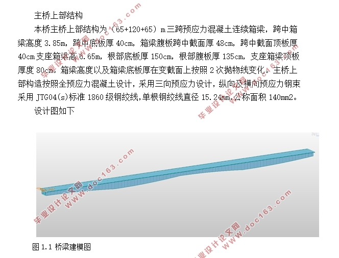
主桥上部结构
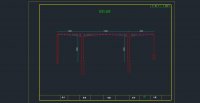
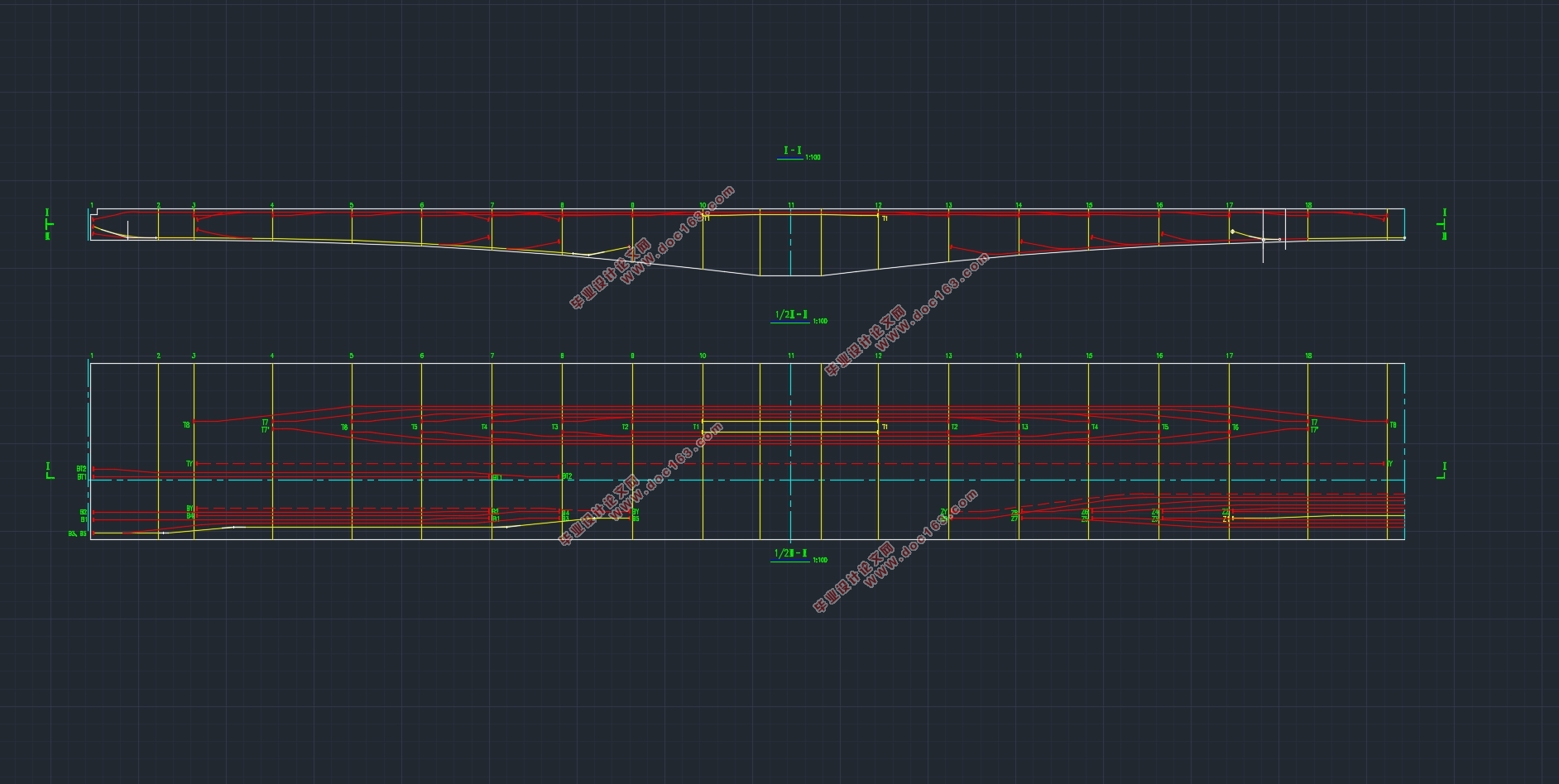
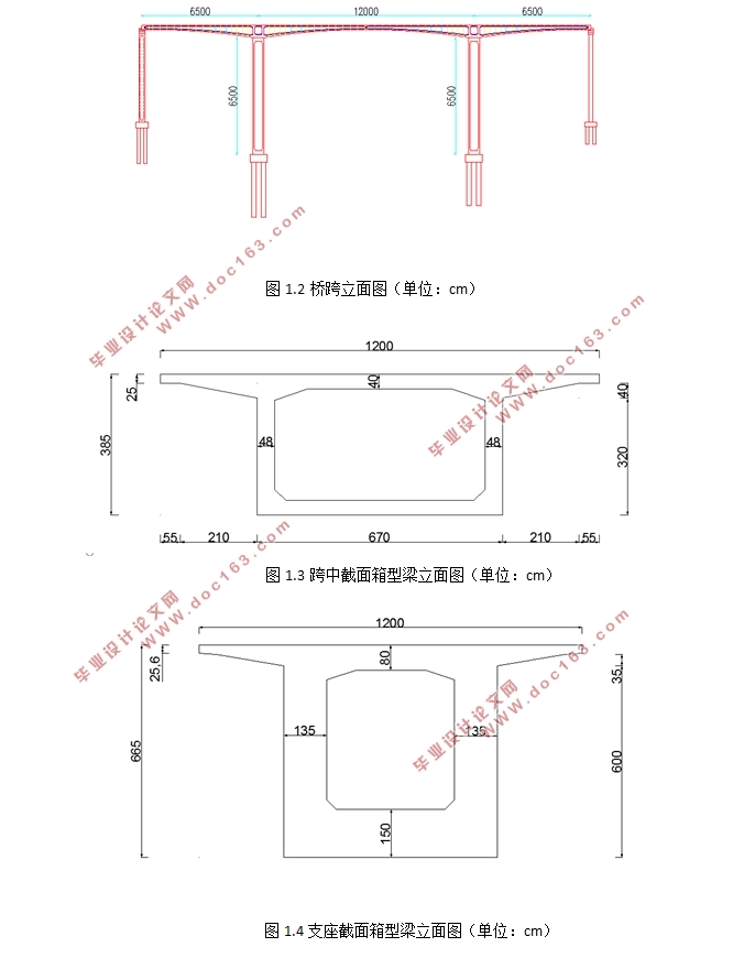
本桥主桥上部结构为(65+120+65)m三跨预应力混凝土连续箱梁,跨中箱梁高度3.85m,跨中底板厚40cm,箱梁腹板跨中截面厚48cm,跨中截面顶板厚40cm支座箱梁高6.65m,根部底板厚150cm,根部腹板厚135cm,支座箱梁顶板厚度80cm。箱梁高度以及箱梁底板厚在变截面上按照2次抛物线变化。主桥上部构造按照全预应力混凝土设计,采用三向预应力设计,纵向及横向预应力钢束采用JTG04(s)标准1860级钢绞线,单根钢绞线直径15.24mm,公称面积140mm2。
设计基准期:100年
荷载等级:公路—Ⅰ级
桥梁宽度:0.5m(防撞护栏)+11.5m(行车道)+2m(中央分隔带)+11.5m(行车道)+0.5m(防撞护栏)=26m。 [版权所有:http://DOC163.com]
[资料来源:https://www.doc163.com]


目录
第一章.工程概述及方案设计 4
1.1工程概述 4
1.2.方案设计 4
第二章.技术标准和规范 6
2.1主要设计规范 6
2.2 主要技术标准 6
第三章.主要材料及设计荷载 7
3.1主要材料及其参数 7
3.1.2预应力钢材 7
3.2恒载 8
3.2.1一期恒载 8
3.2.2二期恒载 8
3.3活载 8
3.4收缩、徐变及温度 8
3.5基础不均匀沉降 8
3.6荷载组合 8
3.7施工荷载 9
第四章.方案比选 10
4.1方案一简支T梁桥 10
4.2方案二连续钢构桥 11
方案三本方案 12
第五章.结构设计与计算、验算 14
5.1主跨内力分析 14 [资料来源:Doc163.com]
5.1.1 按承载能力极限状态设计 14
5.1.2 按正常使用极限状态设计 15
5.1.3 计算结果 16
5.2 结构计算 18
5.2.1 持久状况承载能力极限状态计算 18
5.2.2 持久状况正常使用极限状态计算 20
5.2.3 刚度验算 23
5.2.4 短暂状况(施工阶段)应力计算 24
5.2.5受拉区钢筋拉应力验算 25
5.3 小结 26
第六章.预应力钢束估算及布置 27
6.1 计算原理 27
6.2 预应力筋估算结果 27
6.3 预应力筋布置原则 28
6.4 调束以及预应力钢束布置情况 29
第七章.施工方法比选 31
7.1.平衡悬臂施工法 31
7.2有支架浇筑施工法 33
7.3比较 38
8结论 40
9致谢 41
9参考文献 42 [资料来源:http://doc163.com]
上一篇:5×20m预应力混凝土箱梁桥施工图设计(含CAD图)
下一篇:预应力作用对车桥耦合振动影响分析(含CAD图,ANSYS,MATLAB)