
(65+110+65)m预应力混凝土连续连续刚构箱梁桥设计(含CAD图)
(65+110+65)m预应力混凝土连续连续刚构箱梁桥设计(含CAD图)(任务书,开题报告,外文翻译,论文说明书19000字,CAD图20张)
摘要
本毕业设计为题目为65+110+65m预应力混凝土连续刚构箱梁桥。根据本次毕业设计提供的设计资料,依据现行公路桥梁设计规范,对跨径为 的预应力混凝土连续钢构箱梁桥上、下部结构进行设计计算并完成施工图设计。
首先,根据规范及梁桥构造要求确定主梁的主要构造及细部尺寸。主梁为箱梁结构,箱梁的高度和底板厚度从支点至墩座处呈二次抛物线变化,腹板厚度在边跨跨中和中跨四分之一处呈直线变化,顶板厚度保持不变。本设计考虑到跨径和桥梁的结构形式,采用了矩形双肢薄壁墩。
其次,确定桥梁的施工方法,本设计采用挂篮式悬臂浇筑的施工方法,0号块在墩浇筑完成后,采用支架进行现浇,之后利用挂篮对称浇筑1-11号块,边跨利用满堂支架法现浇完成,然后进行边跨现浇段和0-11号浇筑段合拢,最后进行中跨合拢,形成全桥。
然后,利用Midas/civil软件进行有限元分析。根据已经拟定的桥梁尺寸建立基本模型,进行内力分析、预应力钢筋的调束和布置和截面验算,直至各施工阶段以及成桥只够的使用阶段满足桥梁的基本内力要求和位移要求。最后,对下部结构进行计算和验算,并完成相应图纸的绘制。 [来源:http://www.doc163.com]
通过分析验算表明,本次设计的上、下部结构计算方法正确,内力分布合理,符合设计任务书的要求。
关键词:连续钢构箱梁桥、挂篮式悬臂施工法、Midas/civil、有限元分析
Abstract
This graduation project is entitled 65+110+65m prestressed concrete continuous rigid box girder bridge. According to the graduation design specification requirements, on the basis of the existing highway bridge design code, the span of (65 + 110 + 65) m prestressed concrete continuous steel box girder bridge, the structure of the lower part of design calculations and complete the construction drawing design.
First, the main structure and detail dimensions of the main girder are determined according to the specifications and the structural requirements of the girder bridge. Main girder of box girder structure, the height of the box girder and slab thickness from the fulcrum to block a quadratic parabola changes, web plate thickness in side span cross neutralization across a quarter of the change is linear, the roof thickness remains constant. The design takes into account the structure of span and bridge, and adopts rectangular double-leg thin-walled pier. [版权所有:http://DOC163.com]
Second, determine the construction method of bridge, this design USES the hanging basket cantilever pouring construction method, 0 blocks in the block casting, after the completion of the stent for cast-in-situ, symmetrical casting using hanging basket after 1-11 block, side span with full framing method cast-in-situ completed, then the side span cast-in-place folded and 0 to 11, casting, finally underway across fold, forming the whole bridge.
Then, Midas/civil software is used for finite element analysis. According to establish the basic model has proposed bridge size, internal force analysis, and cross section calculation of prestressed beams and arrangement, until each construction stage as well as the use phase of only enough to meet basic internal force and displacement of the requirements of the bridge. Finally, calculate and check the lower structure, and complete the drawing of the corresponding drawings.
Through analysis and calculation, it is shown that the calculation method of upper and lower structures in this design is correct, and the distribution of internal forces is reasonable.
[版权所有:http://DOC163.com]
Key words: continuous steel box girder bridge, hanging basket cantilever construction method, Midas/civil, finite element analysis
技术标准
设计行车速度:80Km/h。
荷载等级:Ⅰ级。
桥面宽度:桥宽W=0.5+11+0.5=12m。
桥面横坡:单向2%(半幅桥)。
高程系统:黄海高程系统。
坐标系:北京坐标系。
地震烈度:
洪水频率:本设计桥梁桥址位于山谷,主桥为高架桥,洪水影响不需要考虑。
[版权所有:http://DOC163.com]

目录
第1章 绪论 1
1.1 预应力混凝土连续刚构箱梁桥简介 1
1.2 选题设计的意义 1
1.3 设计资料 1
1.3.1 设计规范 1
1.3.2 技术标准 2
1.3.3 地质 2
1.3.4 主要材料 2
第2章 桥型方案比选 4
2.1 构思宗旨 4
2.2 比选原则 4
2.3 方案比选 4
第3章 桥跨布置及结构尺寸拟定 6
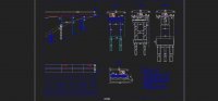
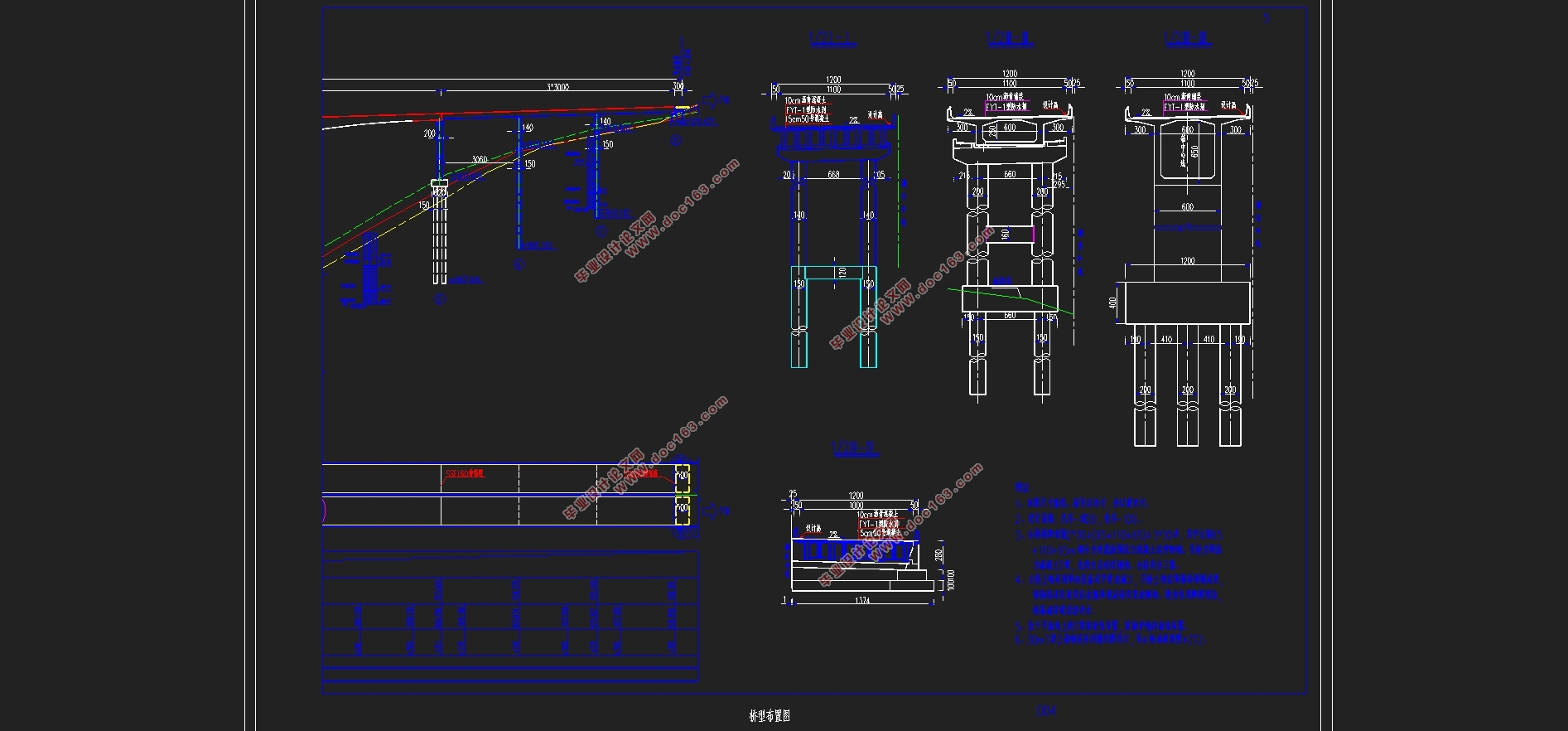
3.1 桥型布置 6
3.2 上部结构尺寸拟定 6
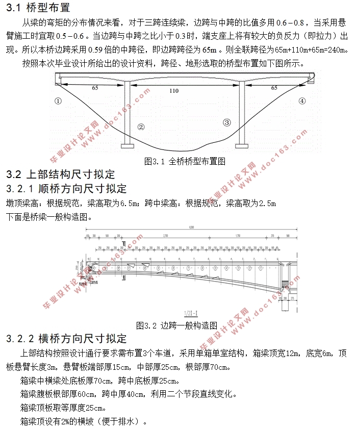
3.2.1 顺桥方向尺寸拟定 6
3.2.2 横桥方向尺寸拟定 6
3.3 下部结构尺寸拟定 8
3.3.1 墩身尺寸拟定 8
3.3.2 桩基础尺寸拟定 8
3.3.3 承台尺寸拟定 9
第4章 建模 10
4.1 模型 10
[来源:http://www.doc163.com]
4.2 主要参数 10
4.2.1 材料参数 10
4.2.2 荷载参数 11
4.2.3 边界条件 12
4.3 施工阶段 12
第5章 桥梁结构内力计算 14
5.1 毛截面几何特性 14
5.2 恒载内力 14
5.3 活载内力计算 18
5.4 次内力计算 21
5.4.1 温度引起的次内力 21
5.4.2支座沉降引起的内力计算 22
5.4.3 收缩徐变引起的内力计算 24
5.5 承载能力极限状态的内力组合 26
5.6 正常使用极限状态的内力组合 27
5.6.1 频遇组合 27
5.6.2 准永久组合 27
5.7 内力组合 27
第6章 预应力钢束数量及损失计算 34
6.1预应力钢束数量确定 34
6.2 预应力钢束的布置 38
6.2.1 布置原则 38 [资料来源:http://Doc163.com]
6.2.2 钢束布置 39
6.3 钢束预应力损失的估算 40
6.4 预应力钢束有效应力计算 42
第7章 主梁验算 43
7.1持久状况承载力极限状态验算 43
7.2 持久状况正常使用极限状态验算 46
7.3 短暂状况构应力验算 50
7.4 正截面受拉区预应力钢束拉应力验算 56
第8章 下部结构计算 58
8.1 桥墩计算 58
8.1.1 荷载计算 58
8.1.2截面配筋计算 59
8.1.3 截面验算 60
8.2 桩计算 61
8.2.1 钻孔桩材料 61
8.2.2 荷载计算 61
8.2.3 桩长计算 61
8.2.4 桩的内力计算(m法) 62
8.2.4.5 基础位移计算 64
8.2.5 桩基配筋计算及桩身材料截面强度验算 64
8.2.5.1 桩身最大弯矩及其位置 64 [资料来源:www.doc163.com]
8.2.5.2桩身配筋计算 64
8.3.5.3截面复核 65
参考文献 67
致谢 68
上一篇:4×30m预应力混凝土连续T梁桥施工图设计(含CAD图)